STARTING/CHARGING
Charging Wiring Diagram for Oldsmobile Silhouette GLS 2000

List of elements for Charging Wiring Diagram for Oldsmobile Silhouette GLS 2000:
- (left of starter) g110
- (not used)
- (or red)
- (right inner fender near battery) g101
- Alt/sense fuse 10a
- Batt
- Battery
- Battery indicator
- Class 2 (pcm)
- Class 2 serial data
- Class 2 serial data line
- Computer data lines
- E12
- Fuse block (right side of dash, in right front door opening)
- Fusible link a (10 ga- rust)
- Generator
- Generator terminal l output
- Hot at all times
- Hot in run, bulb test or start
- Ign 1 fuse 10a
- Ign 1 voltage
- Instrument cluster
- Micro- processor
- Pnk
- Power distribution system
- Powertrain control module (pcm) (secured in air cleaner assembly, left front of engine compartment)
- Red
- S209 (dash harness, center of dash approximately 8 cm (3 in) from
- Security indicator lamp breakout)
- Splice pack sp205 (below steering column, bottom of knee bolster)
- Starter assembly
- Underhood accessory wiring junction block (on right front of engine compartment)
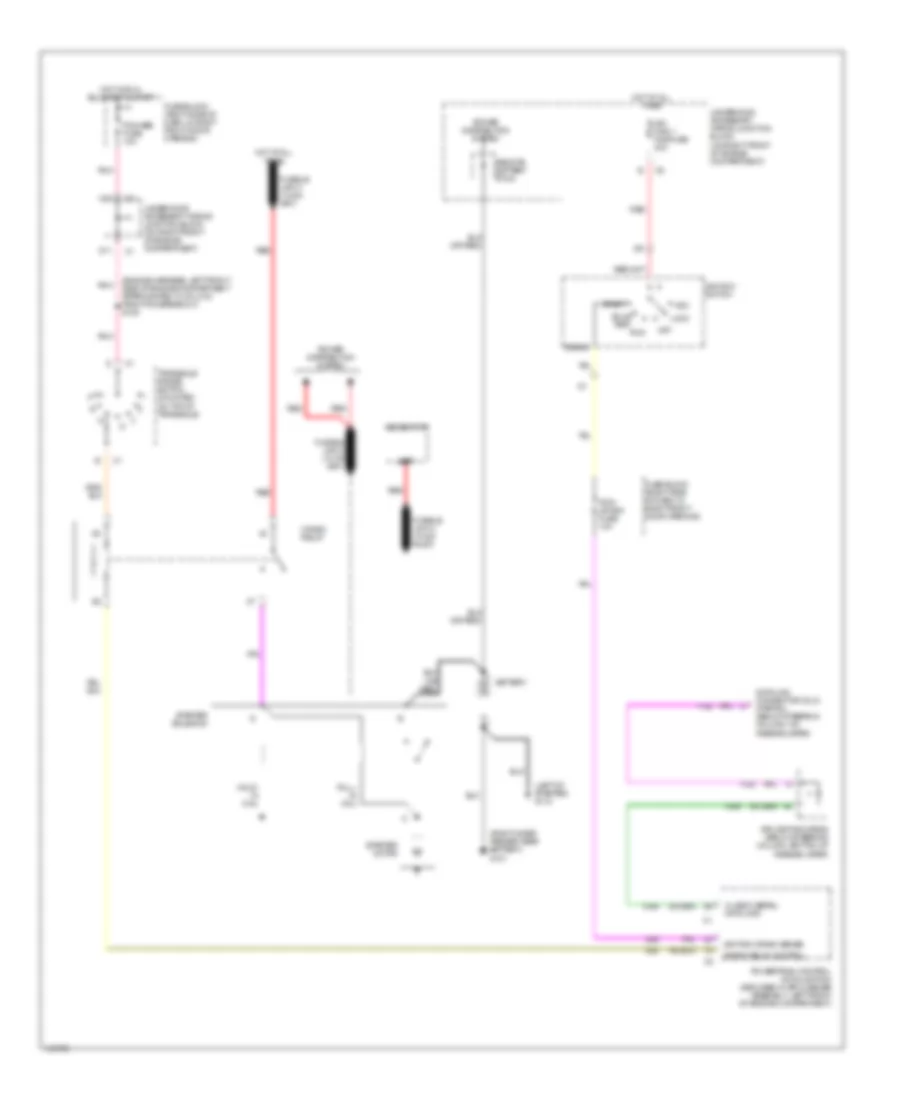
Starting Wiring Diagram for Oldsmobile Silhouette GLS 2000
List of elements for Starting Wiring Diagram for Oldsmobile Silhouette GLS 2000:
- (engine harness, left front side of engine compartment approximately 8 cm (3 in) from pcm breakout) s108
- (left of starter) g110
- (right inner fender near battery) g101
- Acc
- Batt
- Battery
- Bulb test
- C10
- Class 2 serial data line
- Crank
- Crank relay
- Crank relay control
- D11
- Data link connector (dlc) (partial) (below steering column, on knee bolster)
- Fuse block (right side of dash, in right front door opening)
- Fusible link a (10-ga rust)
- Generator
- Hold- in coil
- Hot at all times
- Hot in run, bulb test & start
- Ign main 1 maxifuse 40a
- Ignition crank sense
- Ignition switch
- Lock
- Off
- Pcm/ crank fuse 10a
- Pcm/abs fuse 10a
- Pnk
- Power distribution system
- Powertrain control module (pcm) (secured in air cleaner assembly, left front of engine compartment)
- Pull- in coil
- Red
- Remote battery stud
- Run
- Splice pack sp205 (below steering column, bottom of knee bolster)
- Start
- Starter motor
- Starter solenoid
- Transaxle range switch (mounted on top of transaxle)
- Underhood accessory wiring junction block (on right front of engine compartment)