STARTING/CHARGING
Charging Wiring Diagram for Pontiac Bonneville SSE 1994

List of elements for Charging Wiring Diagram for Pontiac Bonneville SSE 1994:
- *u2e/ub3 clusters **u50/u2f clusters
- a13, b13
- (not used)
- (not used) p
- (right front of engine compt, above right horn)
- (top right front of engine, under ei module)
- 15a
- Bat
- Battery
- Field (rotor)
- Fuse 1d
- G101
- G119
- Gen ctrl
- Generator (top right side of engine)
- Ground distribution
- Hot in run, bulb test or start
- I/p fuse block
- Instrument cluster
- Low voltage input
- Pnk
- Pnk a6, a7
- Pnk b2
- Power distribution
- Powertrain control module (behind right side of i/p, near shroud)
- Rectifier bridge
- Red
- Regulator
- Solid state
- Starter solenoid (lower left front of engine)
- Stator
- U2e/u2f clusters
- Ub3/u50 clusters
- Volt ind.
- Volts lp
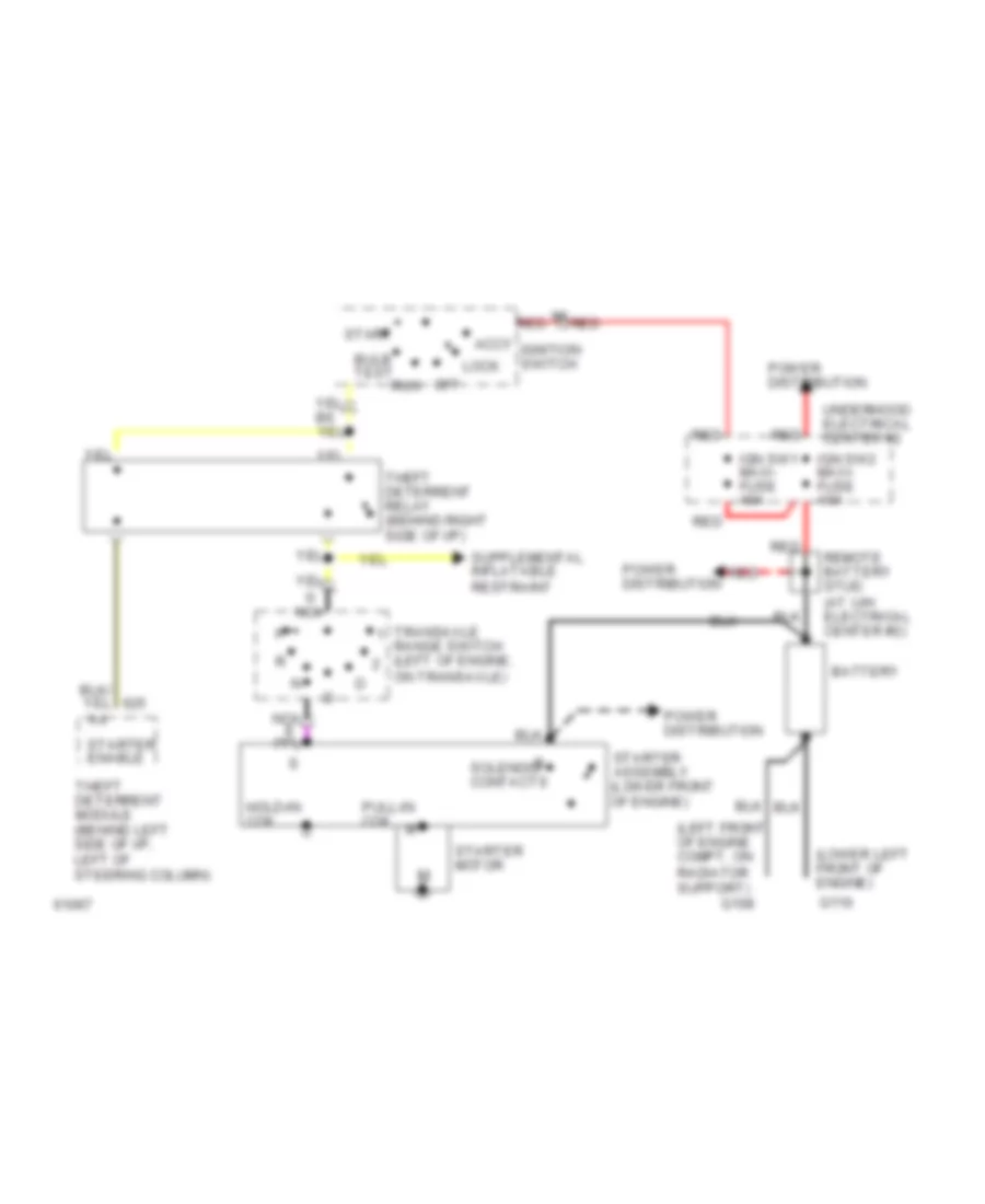
Starting Wiring Diagram for Pontiac Bonneville SSE 1994
List of elements for Starting Wiring Diagram for Pontiac Bonneville SSE 1994:
- (left front of engine compt, on radiator support)
- (lower left front of engine)
- Accy
- Battery
- Bulb test
- G108
- G110
- Hold-in coil
- Ign sw1 maxi- fuse 40a
- Ign sw2 maxi- fuse 40a
- Ignition switch
- Lock
- Nca
- Off
- Power distribution
- Pull-in coil
- Red
- Remote battery stud (at u/h electrical center #2)
- Run
- Solenoid contacts
- Start
- Starter assembly (lower front of engine)
- Starter enable
- Starter motor
- Theft deterrent module (behind left side of i/p, left of steering column)
- Theft deterrent relay (behind right side of i/p)
- Transaxle range switch (left of engine, on transaxle)
- Underhood electrical center #2