STARTING/CHARGING
Charging Wiring Diagram for Pontiac G6 GXP 2008

List of elements for Charging Wiring Diagram for Pontiac G6 GXP 2008:
- (not used)
- (on left rear side of engine compt, on engine transmission stud, below upper coolant hose)
- 2.4l
- 3.5l & 3.9l
- 3.6l
- 5-volt ref
- 5-volt reference
- Battery
- Battery current sensor (3.6l)
- Battery current sensor signal
- Body control module (bcm) (under right side of center console, near dash)
- Charge ind
- Computer data lines system
- Ecm/pcm serial data
- Engine control module (ecm) (left side of engine compt)
- Except 2.4l
- G104 (on left side of engine compt, on core support, between left inflatable restraint front end sensor & g109)
- G105
- Generator
- Generator field duty cycle signal
- Generator turn on signal
- High speed gmlan serial data bus +
- High speed gmlan serial data bus -
- Ign
- Instrument panel cluster (ipc)
- Logic
- Low ref
- Low reference
- Low speed gmlan serial data
- Pnk
- Power distribution system
- Red
- Starter
- Tan
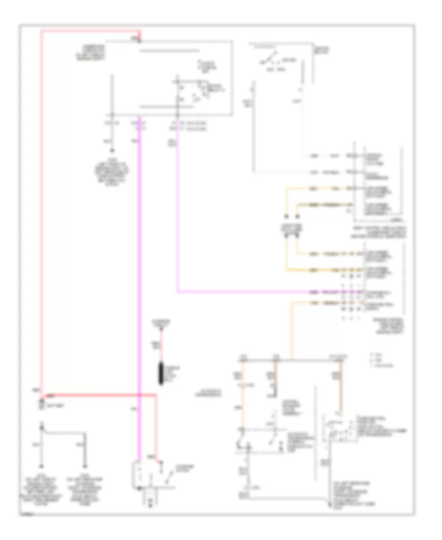
Starting Wiring Diagram for Pontiac G6 GXP 2008
List of elements for Starting Wiring Diagram for Pontiac G6 GXP 2008:
- (2.4l & 3.6l)
- (3.5l & 3.9l)
- (on left rear side of engine compt, on engine transmission stud, below upper coolant hose) g105
- 2.4l
- 2.4l & 3.5l (a/t)
- 3.5l & 3.9l
- 3.6l
- 3.6l (a/t)
- 3.9l (a/t)
- 5-volt reference
- A x1
- Automatic transmission
- Automatic transmission internal mode switch (ims)
- Battery
- Body control module (bcm) (under right side of center console, near dash)
- C1 x2
- C10 x2
- Charging circuit
- Computer data lines system
- Control solenoid valve assembly
- D12 x1
- Engine control module (ecm) (left side of engine compt)
- G104 (on left side of engine compt, on core support, between left inflatable restraint front end sensor & g109)
- G105 (on left rear side of engine compt, on engine transmission stud, below upper coolant hose)
- G109 (left front of engine compt, on left rear side of core support, between g101 & g104)
- High speed gmlan serial data bus +
- High speed gmlan serial data bus -
- Ignition switch
- K x100
- Logic
- Nca
- Off
- Off/run/ crank voltage
- Park/neutral position (pnp) switch (below master cylinder, on transmission)
- Park/neutral signal
- Red
- Run acc
- Start
- Starter motor
- Starter rly coil ctrl
- Strtr fuse 26 30a
- Strtr relay 31
- Tan
- Underhood fuse block (in left side of engine compt)
- W x100
- X1 e12