STARTING/CHARGING
Charging Wiring Diagram for Pontiac Montana SV6 2005

List of elements for Charging Wiring Diagram for Pontiac Montana SV6 2005:
- Battery
- Battery current sensor (right front of eng comt, near battery)
- Battery ind
- Body control module (bcm) (below left side of dash, left of steering column)
- Class 2 serial data
- Clstr/ hvac fuse 8 10a
- Computer data lines
- Current sens sig
- Current sensor
- G102 (right of eng fuse block)
- G115 (at eng to transmission stud nearest starter)
- Gen field duty cycle sign
- Gen turn on sig
- Generator
- Ground
- Hot at all times
- I/p dimming voltage ref
- I/p fuse block (right side of dash)
- Ign 1 volt
- Instrument panel cluster
- Interior light system
- Low ref
- Power distribution system
- Powertrain control module (on left front of eng compt, in air cleaner assembly)
- Red
- S257 (dash harn, 8.5 cm from breakout for ipc toward right side of dash)
- Sp205 (near headlamp switch connector, behind left dash, on dash harn)
- Starter motor
- Underhood fuse block (above right front wheelwell)
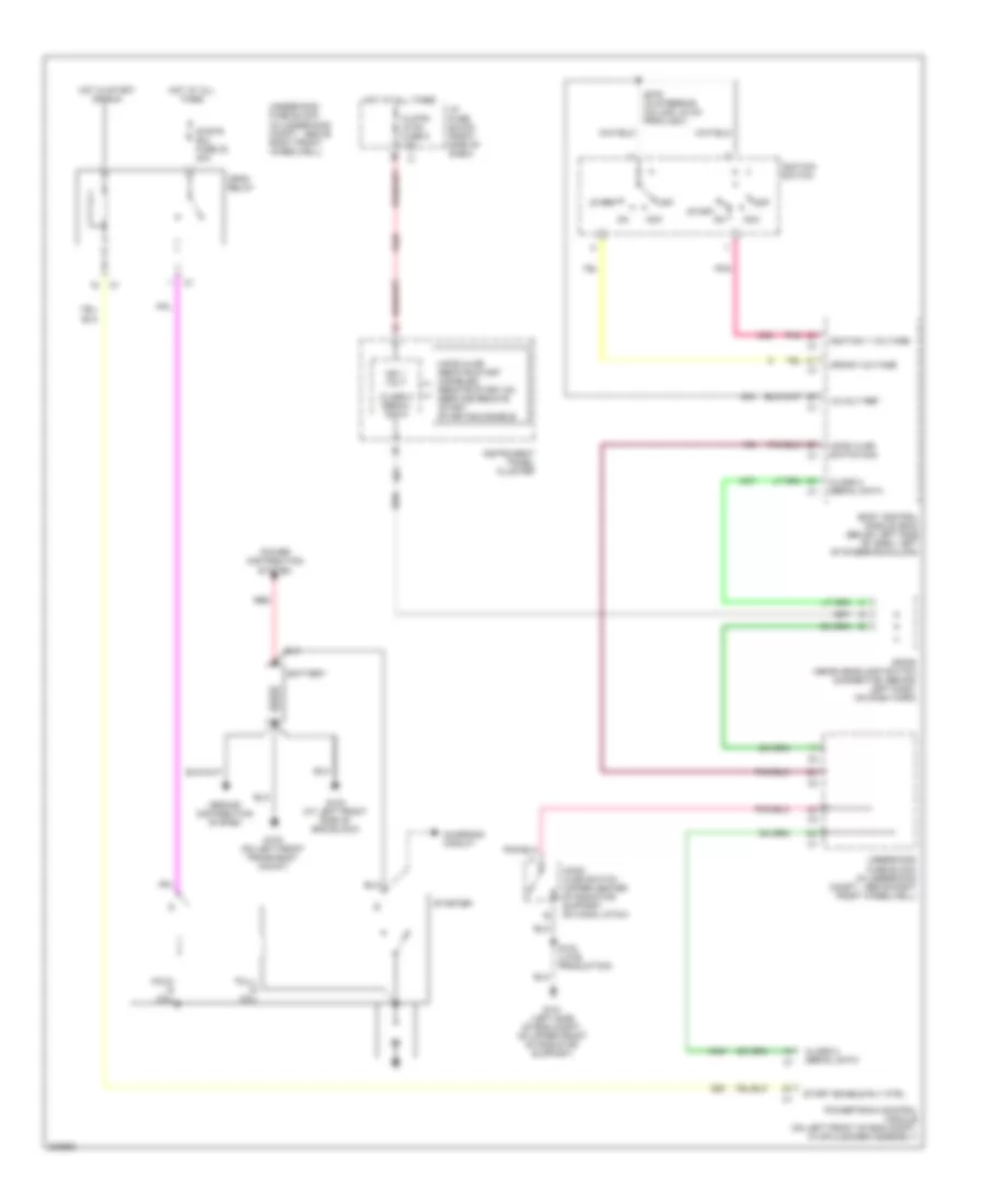
Starting Wiring Diagram for Pontiac Montana SV6 2005
List of elements for Starting Wiring Diagram for Pontiac Montana SV6 2005:
- -hood ajar -remote start disabled -remote start on -service remote start -starting disable
- 12-volt ref
- Acc
- Battery
- Body control module (bcm) (below left side of dash, left of steering column)
- Charging circuit
- Class 2 serial data
- Clstr/ hvac fuse 8 10a
- Crank voltage
- Crnk relay
- G100 (on left front frame body mount)
- G101 (left side of eng compt, on upper front of radiator support)
- G102 (at left front side of eng block)
- Ground distribution system
- Hold- in coil
- Hood ajar switch (upper center of radiator support, on hood latch)
- Hood ajar switch sig
- Hot at all times
- Hot in start or run
- I/p fuse block (right side of dash)
- Ign 1 volt
- Ignition 1 voltage
- Ignition switch
- Instrument panel cluster
- Off
- Pnk
- Power distribution system
- Powertrain control module (on left front of eng compt, in air cleaner assembly)
- Pull- in coil
- Red
- S103 (late production)
- S279 (in steering column, 20 cm from c201)
- Sp205 (near headlamp switch connector, behind left dash, on dash harn)
- Start
- Start enable rly ctrl
- Starter
- Strtr sol fuse 30 40a
- Underhood fuse block (in underhood compt, above right front wheelwell)