STARTING/CHARGING
Charging Wiring Diagram for Porsche 911 Carrera 2009

List of elements for Charging Wiring Diagram for Porsche 911 Carrera 2009:
- B+ plug socket (near right side of transmission)
- Battery
- Coupe
- Current distributor (behind right side of dash)
- Dme control unit (left front of engine compt)
- Engine controls system
- Generator
- Gp13 (at battery)
- Ground distribution system
- Red
- Starter
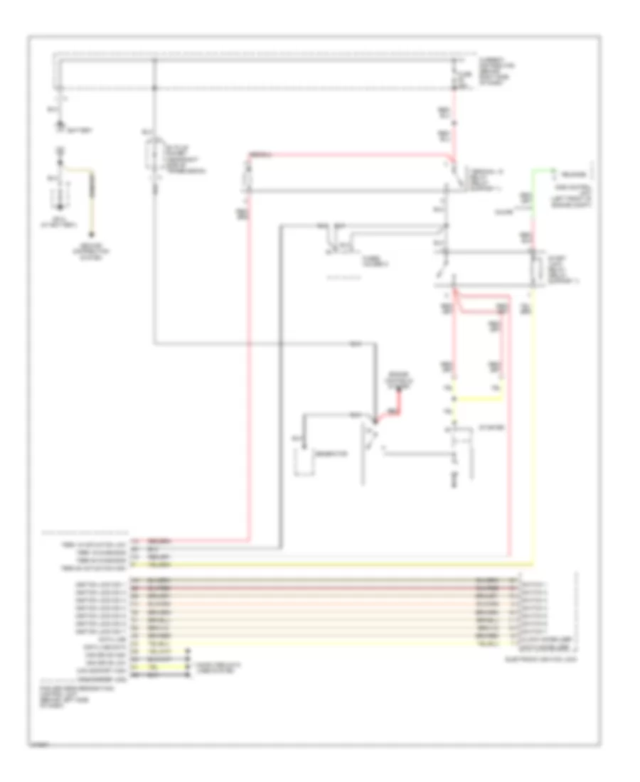
Starting Wiring Diagram for Porsche 911 Carrera 2009
List of elements for Starting Wiring Diagram for Porsche 911 Carrera 2009:
- B+ plug socket (near right side of transmission)
- Battery
- Can comfort high
- Can comfort low
- Can drive high
- Can drive low
- Clock immobilizer
- Computer data lines system
- Coupe
- Current distributor (behind right side of dash)
- Data immobilizer
- Data line
- Data line data
- Dme control unit (left front of engine compt)
- Electronic ignition lock
- Engine controls system
- Fuse f6 80a
- Fuses holder c
- Generator
- Gp13 (at battery)
- Ground distribution system
- Ignition lock sw 1
- Ignition lock sw 2
- Ignition lock sw 3
- Ignition lock sw 4
- Ignition lock sw 5
- Ignition lock sw 6
- Ignition lock sw 7
- Pas (driver's recognition) control unit (behind left side of dash)
- Red
- Release
- Start lock relay (relay support 1)
- Starter
- Switch 1
- Switch 2
- Switch 3
- Switch 4
- Switch 5
- Switch 6
- Switch 7
- Term 15 actuation low
- Term 15 diagnosis
- Term 50 actuation high
- Term 50 diagnosis
- Terminal 15 relay (relay support 1)