STARTING/CHARGING
Charging Wiring Diagram for Toyota 4Runner SR5 1995

List of elements for Charging Wiring Diagram for Toyota 4Runner SR5 1995:
- 2.4l w/ a/t
- Alt fuse 80a 100a
- Am1 fuse 40a
- Battery
- Battery ground
- Charge warning light
- Comb- ination meter
- Daytime runn- ing light relay main (canada) (behind right side of dash)
- Engine fuse 10a
- Except 2.4l w/ a/t
- Generator
- Hot in on or start
- I9 (i/p harness, behind center of a/c vents)
- Ign fuse 7.5a
- J/b 1 (on left kick panel)
- Nca
- R/b 2 (on right side of engine compt)
- Red
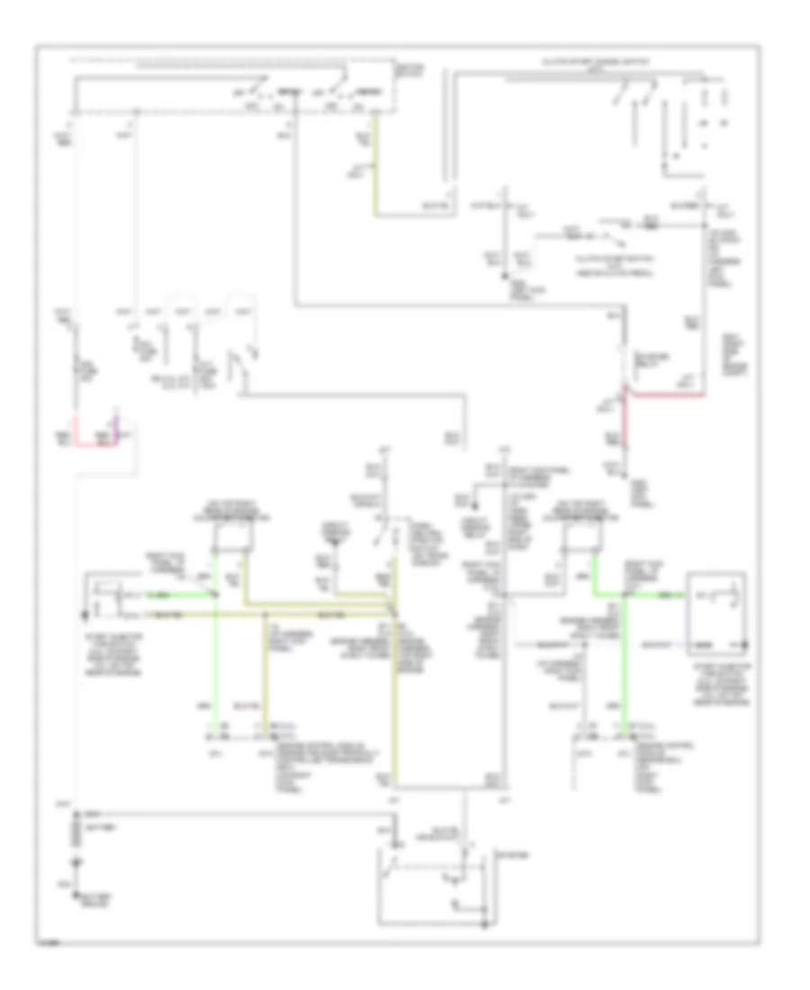
Starting Wiring Diagram for Toyota 4Runner SR5 1995
List of elements for Starting Wiring Diagram for Toyota 4Runner SR5 1995:
- (2.4l)
- (3.0l)
- (3.0l) (engine harness, top right side of engine)
- (ex 2.4l a/t) (2.4l a/t)
- (on top right rear of engine) cold start injector
- (right kick panel, i/p harness) (3.0l) i15
- (right kick panel, i/p harness) (3.ol) i15
- (right kick panel, i/p harness) i14 (canada)
- (right kick panel, i/p harness) i15
- A/t
- A/t only
- Acc
- Alt fuse 80a 100a
- Am1 fuse 40a
- Am2 fuse 30a
- Battery
- Battery ground
- Circuit opening relay
- Clutch start cancel switch (m/t)
- Clutch start switch (m/t) (above clutch pedal)
- E11 (2.4) (engine harness, right front strut tower)
- E4 e11 (2.4) (engine harness, right front strut tower)
- Engine control module (engine and electronically controlled transmission ecu) (on right kick panel)
- Engine control module (engine ecu) (on right kick panel)
- G200 (left kick panel)
- I12 (usa) (i/p harn- ness, upper right end of dash)
- I15 (i/p harness, right kick panel)
- I16 (usa) i20 (cana- da) (i/p harness, left kick panel)
- Ignition switch
- M/t
- M/t only
- Nca
- Off
- P/ n
- Park/ neutral position switch (on trans- mission)
- R/b 2 (right side of engine compt)
- Sta
- Start
- Start injector time switch (2.4l: on right side of engine; 3.0l: on top rear of engine)
- Starter
- Starter relay
- Stj