STARTING/CHARGING
1.9L TURBO DIESEL
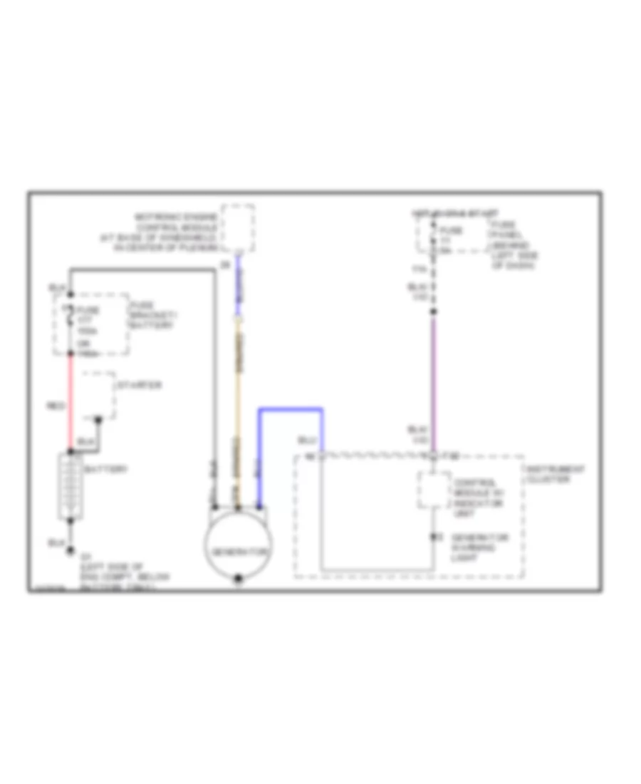
1.9L Turbo Diesel, Charging Wiring Diagram for Volkswagen Golf GL 2006

List of elements for 1.9L Turbo Diesel, Charging Wiring Diagram for Volkswagen Golf GL 2006:
- 11a
- B1+
- Battery
- Control module w/ indicator unit
- Dfm
- Diesel direct fuel injection engine control module (at base of windshield, in center of plenum)
- Fuse 150a
- Fuse 5a
- Fuse bracket/ battery
- Fuse panel (behind left side of dash)
- G1 (left side of eng compt, below battery tray)
- Generator
- Generator warning light
- Hot in on & start
- Instrument cluster
- Red
- Starter
- T32
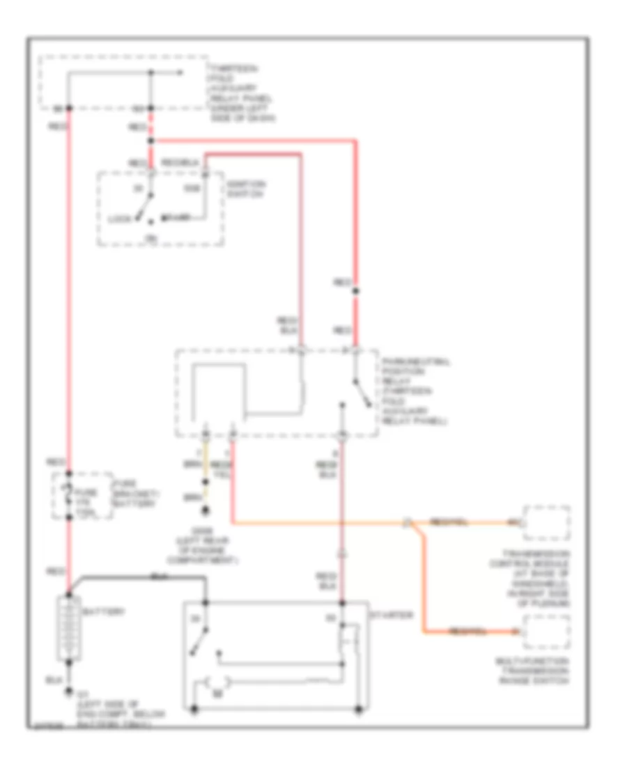
1.9L Turbo Diesel, Starting Wiring Diagram, A/T for Volkswagen Golf GL 2006
List of elements for 1.9L Turbo Diesel, Starting Wiring Diagram, A/T for Volkswagen Golf GL 2006:
- 50b
- Battery
- Fuse 110a
- Fuse bracket/ battery
- G1 (left side of eng compt, below battery tray)
- G608 (left rear of engine compartment)
- Ignition switch
- Lock
- Multi-function transmission range switch
- Park/neutral position relay (thirteen- fold auxiliary relay panel)
- Red
- Start
- Starter
- Thirteen- fold auxiliary relay panel (under left side of dash)
- Transmission control module (at base of windshield, in right side of plenum)
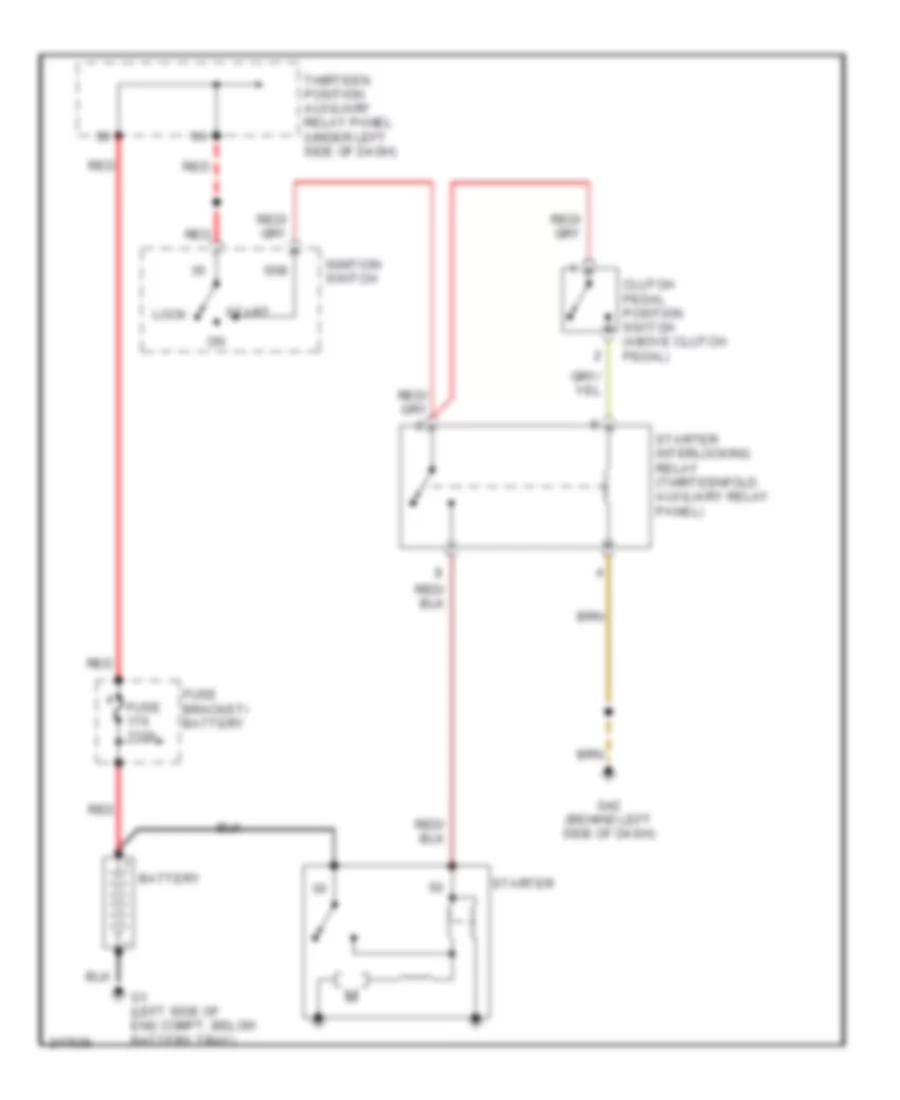
1.9L Turbo Diesel, Starting Wiring Diagram, M/T for Volkswagen Golf GL 2006
List of elements for 1.9L Turbo Diesel, Starting Wiring Diagram, M/T for Volkswagen Golf GL 2006:
- 50b
- Battery
- Clutch pedal position switch (above clutch pedal)
- Fuse 110a
- Fuse bracket/ battery
- G1 (left side of eng compt, below battery tray)
- G42 (behind left side of dash)
- Ignition switch
- Lock
- Red
- Start
- Starter
- Starter interlocking relay (thirteenfold auxiliary relay panel)
- Thirteen position auxiliary relay panel (under left side of dash)
2.0L
2.0L, Charging Wiring Diagram for Volkswagen Golf GL 2006
List of elements for 2.0L, Charging Wiring Diagram for Volkswagen Golf GL 2006:
- 11a
- B1+
- Battery
- Control module w/ indicator unit
- Dfm
- Fuse 150a
- Fuse 5a
- Fuse bracket/ battery
- Fuse panel (behind left side of dash)
- G1 (left side of eng compt, below battery tray)
- Generator
- Generator warning light
- Hot in on & start
- Instrument cluster
- Motronic engine control module (at base of windshield, in center of plenum)
- Or 110a
- Red
- Starter
- T32
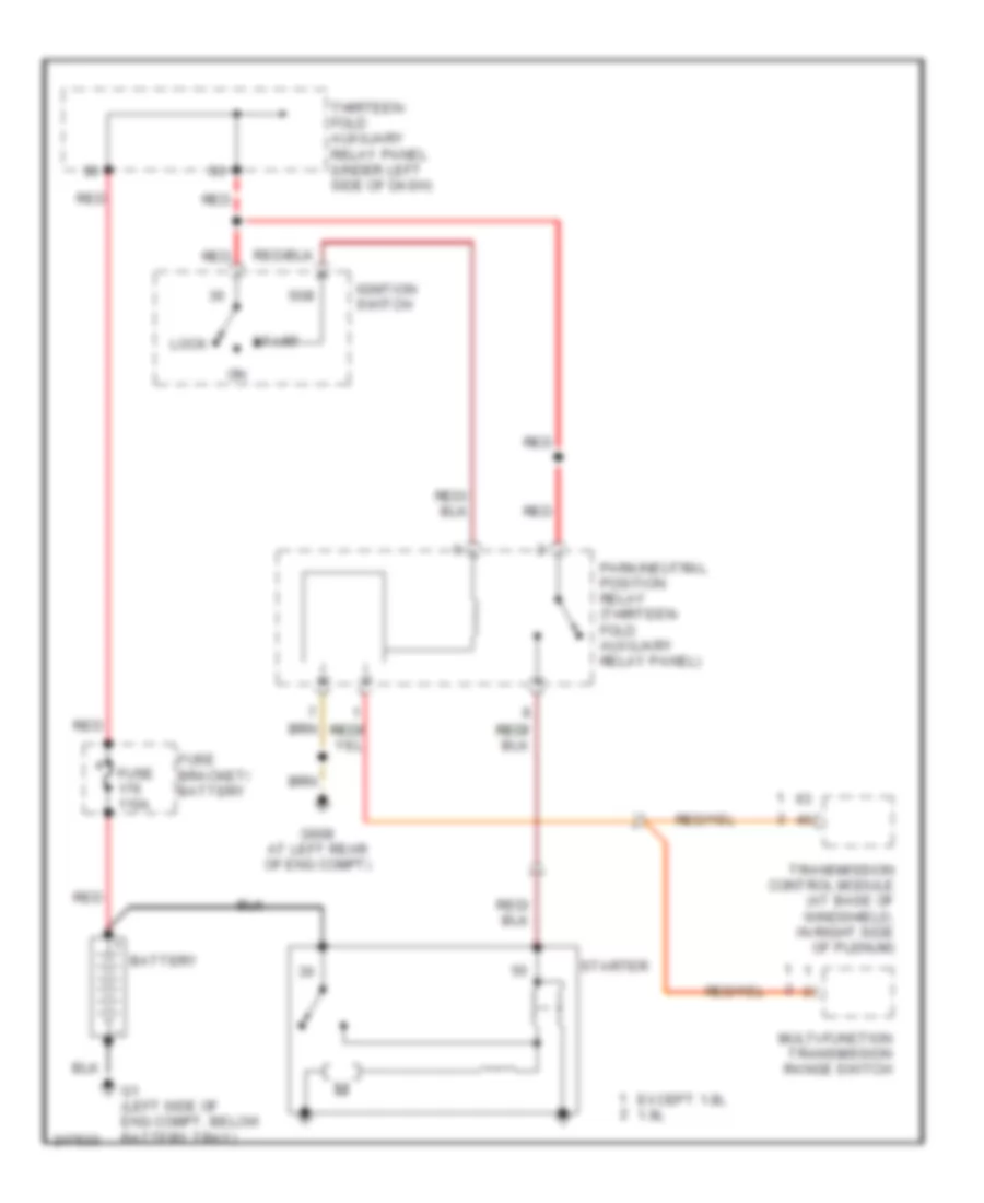
2.0L, Starting Wiring Diagram, A/T for Volkswagen Golf GL 2006
List of elements for 2.0L, Starting Wiring Diagram, A/T for Volkswagen Golf GL 2006:
- 50b
- Battery
- Except 1.8l 1.8l
- Fuse 110a
- Fuse bracket/ battery
- G1 (left side of eng compt, below battery tray)
- G608 at left rear of eng compt)
- Ignition switch
- Lock
- Multi-function transmission range switch
- Park/neutral position relay (thirteen- fold auxiliary relay panel)
- Red
- Start
- Starter
- Thirteen- fold auxiliary relay panel (under left side of dash)
- Transmission control module (at base of windshield, in right side of plenum)
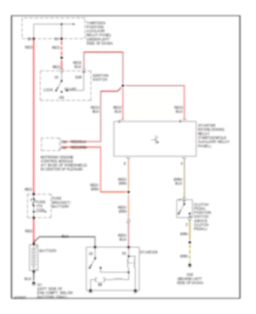
2.0L, Starting Wiring Diagram, M/T Engine Code BBW for Volkswagen Golf GL 2006
List of elements for 2.0L, Starting Wiring Diagram, M/T Engine Code BBW for Volkswagen Golf GL 2006:
- 50b
- Battery
- Clutch pedal position switch (above clutch pedal)
- Fuse 110a
- Fuse bracket/ battery
- G1 (left side of eng compt, below battery tray)
- G42 (behind left side of dash)
- Ignition switch
- Lock
- Motronic engine control module (at base of windshield, in center of plenum)
- Red
- Start
- Starter
- Starter interlocking relay (thirteenfold auxiliary relay panel)
- Thirteen position auxiliary relay panel (under left side of dash)
2.0L, Starting Wiring Diagram, M/T Except Engine Code BBW for Volkswagen Golf GL 2006
List of elements for 2.0L, Starting Wiring Diagram, M/T Except Engine Code BBW for Volkswagen Golf GL 2006:
- 50b
- Battery
- Clutch pedal position switch (above clutch pedal)
- Fuse 110a
- Fuse bracket/ battery
- G1 (left side of eng compt, below battery tray)
- G42 (behind left side of dash)
- Ignition switch
- Lock
- Red
- Start
- Starter
- Starter interlocking relay (thirteenfold auxiliary relay panel)
- Thirteen position auxiliary relay panel (under left side of dash)