STARTING/CHARGING
Charging Wiring Diagram for Volvo V50 2005

List of elements for Charging Wiring Diagram for Volvo V50 2005:
- 150a
- Battery
- Battery temperature sensor (under battery, in battery tray)
- Central electronic module (behind right side of dash)
- Engine control module (2.4l) (left front of engine compartment)
- Engine control module (2.5l turbo) (left front of engine compartment)
- G13
- G3 (at left strut tower)
- G4 (front of battery)
- Generator
- Main fuses (next to battery)
- Pf1
- Red
- Starter motor
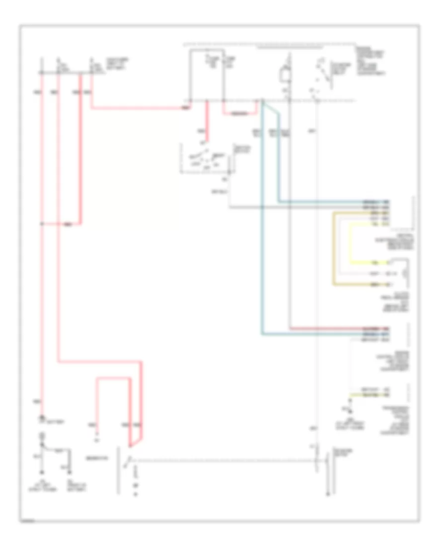
Starting Wiring Diagram for Volvo V50 2005
List of elements for Starting Wiring Diagram for Volvo V50 2005:
- A42
- Acc
- B15
- B17
- Battery
- Central electronic module (behind right side of dash)
- Clutch pedal sensor (m/t) (behind left side of dash)
- Engine compartment distribution box (left side of engine compartment)
- Engine control module (left front of engine compartment)
- Fuse f13 30a
- Fuse f26 15a
- G12
- G21
- G23
- G3 (at left strut tower)
- G4 (front of battery)
- G52 (at left front strut tower)
- Generator
- Ignition switch
- Lock
- Main fuses (next to battery)
- Off
- Pf1 150a
- Pf2 150a
- Red
- Start
- Starter motor
- Starter motor relay
- Transmission control module (a/t) (at rear of engine compartment)
 English