SUPPLEMENTAL RESTRAINTS
Supplemental Restraints Wiring Diagram for Buick Park Avenue 2005
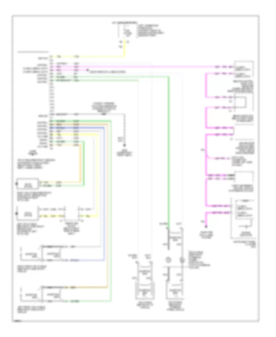
List of elements for Supplemental Restraints Wiring Diagram for Buick Park Avenue 2005:
- (in body harness, 15 cm from sensing & diagnostic module breakout) s307
- A10
- A11
- A12
- A13
- A14
- A15
- A16
- A17
- A18
- Air bag indicator
- B11
- B12
- Case ground
- Class 2 serial data
- Computer data lines system
- Control
- D11
- Data link connector (under left side of dash)
- Driver door module (ddm) (inside driver's door, above radio speaker)
- F11
- F12
- G306 (under right front seat)
- Ground
- Hot in run or start
- Ignition
- Inflatable restraint i/p module
- Inflatable restraint sensing & diagnostic module (sdm) (below right front seat, under carpet)
- Inflatable restraint steering wheel module
- Inflatable restraint steering wheel module coil (top of steering column)
- Instrument panel cluster (ipc)
- Left front inflatable restraint side impact module
- Left inflatable restraint side impact sensor (sis) (on base of left "b" pillar)
- Left underhood fuse block (on right front of engine compartment, near battery)
- Logig
- Nca
- Rear fuse block (below right side of rear seat)
- Remote control door lock receiver (under center of rear package shelf)
- Right front inflatable restraint side impact module
- Right inflatable restraint side impact sensor (sis) (on base of right "b" pillar)
- Shorting bar
- Signal
- Sir fuse 10a
- Solid state
- Tan
- Theft deterrent control module (in steering column)
- Voltage
 English