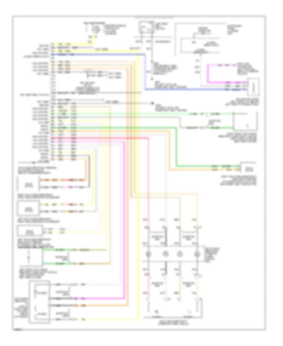
SUPPLEMENTAL RESTRAINTS
Supplemental Restraints Wiring Diagram for Buick Rendezvous CX 2003
List of elements for Supplemental Restraints Wiring Diagram for Buick Rendezvous CX 2003:
- (not used)
- (on left "b" pillar, under seat belt anchor)
- (on right "b" pillar, under seat belt anchor)
- A10
- A11
- A12
- A13
- A14
- A15
- A16
- A17
- A18
- Air bag indicator
- Bar
- Breakout)
- C1 a1
- Center console fuse block (in floor console)
- Class 2 serial data
- Data link connector (dlc) (partial) (below steering column)
- Driver seat
- G301
- G302
- Ground
- High control
- Hot in on & start
- Ign
- Ignition
- Inflatable restraint i/p module (right side of dash, above glove box)
- Inflatable restraint sensing & diagnostic module (below passenger's seat)
- Inflatable restraint steering wheel module
- Inflatable restraint steering wheel module coil
- Instrument panel cluster (ipc)
- Left front inflatable restraint side impact module (left side of driver seat back cover)
- Left inflatable restraint front end discriminating sensor
- Left inflatable restraint side impact sensor (at base of left "b" pillar, above seat belt retractor)
- Left seat belt switch
- Low control
- Nca
- Not used
- Pnk
- Red
- Right front inflatable restraint side impact module (right side of driver seat back cover)
- Right inflatable restraint front end discriminating sensor
- Right inflatable restraint side impact sensor (at base of right "b" pillar, above seat belt retractor)
- Shorting
- Shorting bar
- Signal
- Solid state
- Splice pack sp 315 (inside console, on floor underneath rear air duct)
- Splice pack sp205 (left side of i/p, behind left side i/p access panel)
- Srs fuse 10a
- Stage 1
- Stage 2
- Tan
- Voltage
 English