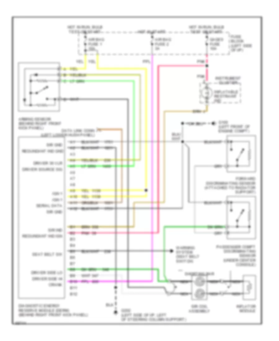
SUPPLEMENTAL RESTRAINTS
Supplemental Restraint Wiring Diagram for Buick Skylark Custom 1995
List of elements for Supplemental Restraint Wiring Diagram for Buick Skylark Custom 1995:
- A10
- A11
- A12
- Air bag fuse 1 15a
- Air bag fuse 2 3a
- Arming sensor (behind right front kick panel)
- B10
- B11
- B12
- Crank
- Diagnostic energy reserve module (derm) (behind right front kick panel)
- Driver 36 vlr
- Driver side hi
- Driver side lo
- Driver source sig
- Forward discriminating sensor (attached to radiator support)
- Fuse block (left side of i/p)
- G100 (left front of engine compt)
- G202 (left side of i/p, left of steering column support)
- Gages fuse 10a
- Hot in run, bulb test or start
- Hot in start
- Ign 1
- Inflatable restraint ind
- Inflator module
- Instrument cluster
- L data link conn (left lower hush panel)
- Nca
- Passenger compt discriminating sensor (under center console)
- Pnk
- Redundant ind gnd
- Redundant ind ign
- Seat belt sw
- Serial data
- Shorting bar
- Sir coil assembly
- Sir gnd
- Sir ind
- Warning system (seat belt switch)
 English