SUPPLEMENTAL RESTRAINTS
Supplemental Restraints Wiring Diagram for Chevrolet Astro 2005
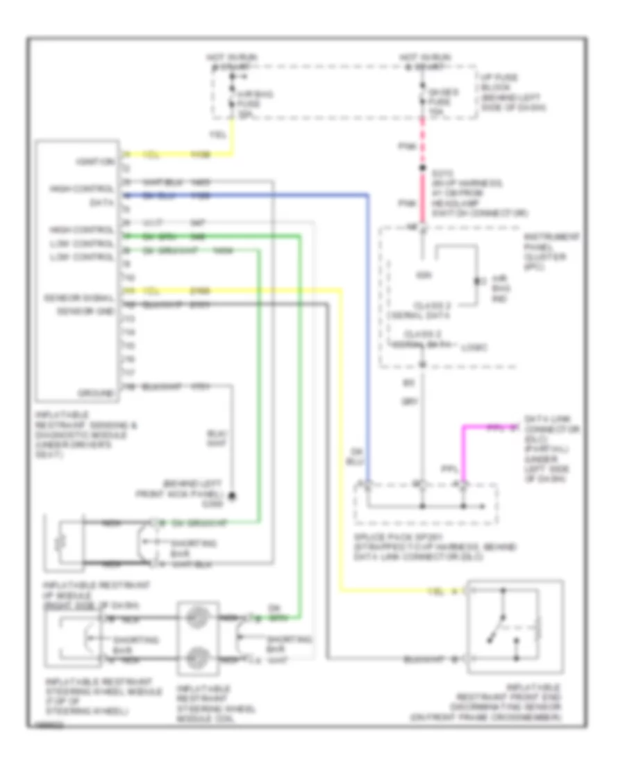
List of elements for Supplemental Restraints Wiring Diagram for Chevrolet Astro 2005:
- (behind left front kick panel) g300
- Air bag fuse 10a
- Air bag ind
- Class 2 serial data
- Data
- Data link connector (dlc) (partial) (under left side of dash)
- Gages fuse 10a
- Ground
- High control
- Hot in run & start
- I/p fuse block (behind left side of dash)
- Ign
- Ignition
- Inflatable restraint front end discriminating sensor (on front frame crossmember)
- Inflatable restraint i/p module (right side of dash)
- Inflatable restraint sensing & diagnostic module (under driver's seat)
- Inflatable restraint steering wheel module (top of steering wheel)
- Inflatable restraint steering wheel module coil
- Instrument panel cluster (ipc)
- Logic
- Low control
- Nca
- Pnk
- S213 (in i/p harness, 41 cm from headlamp switch connector)
- Sensor gnd
- Sensor signal
- Shorting bar
- Splice pack sp261 (strapped to i/p harness, behind data link connector (dlc)
 English