SUPPLEMENTAL RESTRAINTS
Supplemental Restraint Wiring Diagram for Chevrolet Cab & Chassis K2500 1995
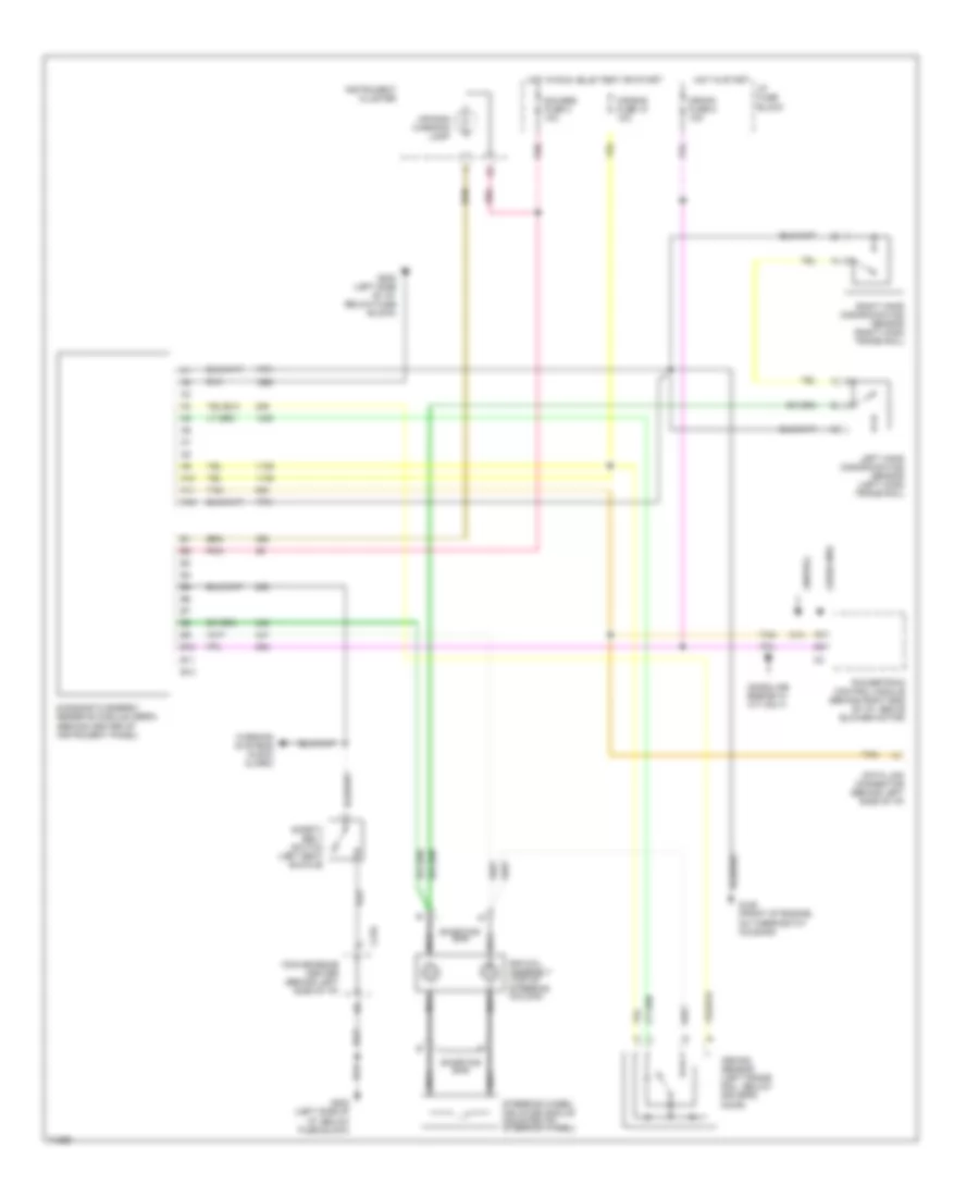
List of elements for Supplemental Restraint Wiring Diagram for Chevrolet Cab & Chassis K2500 1995:
- (diesel)
- (gasoline engine w/ m/t only)
- (gasoline)
- A10
- A11
- A12
- Air bag fuse 10 10a
- Air bag warning lamp
- Arming sensor (left frame rail, below driver's door)
- B10
- B11
- B12
- C14
- C210
- Convenience center (behind left side of i/p)
- Crank fuse 8 10a
- Data link connector (behind left side of i/p)
- Diagnostic energy reserve module (derm) (behind center of instrument panel)
- G125 (front of engine, on thermostat housing)
- G202 (left side of i/p, below fuse block)
- Gauges fuse 4 10a
- Hot in run, bulb test or start
- Hot in start
- I/p fuse block
- Instrument cluster
- Left hand discriminating sensor (left hand frame rail)
- Nca
- Pnk
- Powertrain control module (behind right end of i/p, above blower motor)
- Right hand discriminating sensor (right hand frame rail)
- Safety belt switch (left seat buckle)
- Shorting bar
- Sir coil assembly (top of steering column)
- Steering wheel inflator module (mounted on steering wheel)
- Tan
- Warning systems (audio alarm)
 English