SUPPLEMENTAL RESTRAINTS
Supplemental Restraint Wiring Diagram for Chevrolet Caprice Impala SS 1994
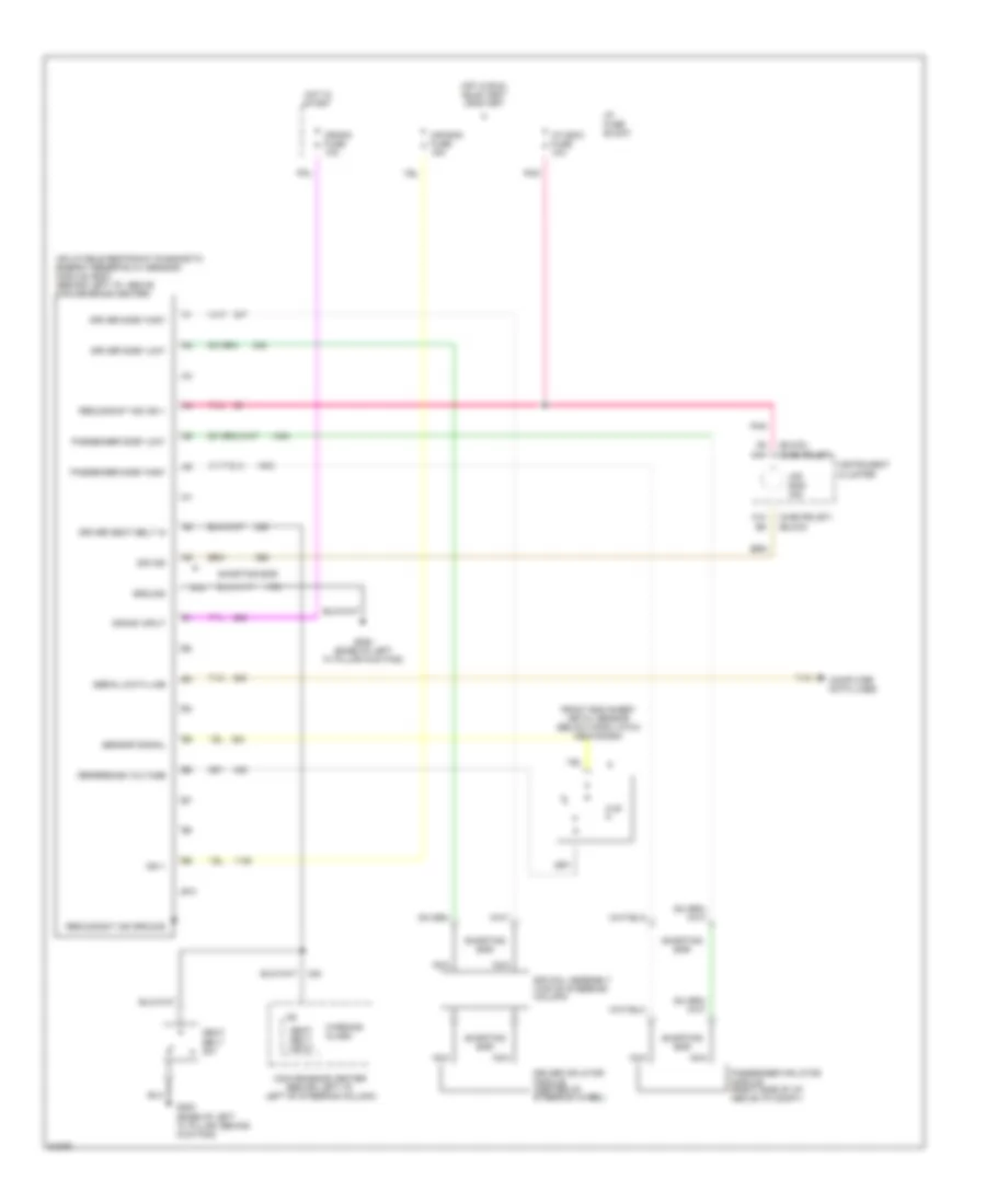
List of elements for Supplemental Restraint Wiring Diagram for Chevrolet Caprice Impala SS 1994:
- (buick)
- (chevrolet)
- 8.45 k
- A10
- A9 a11
- Air bag fuse 15a
- Air bag ind
- B10
- Computer data lines
- Comvenience center (behind left i/p, left of steering column)
- Crank fuse 10a
- Crank input
- Driver inflator module (center of steering wheel)
- Driver seat belt in
- Driver side "high"
- Driver side "low"
- Front end sheet metal sensor (below hood latch mechanism)
- G200 (base of left "a" pillar kick pad)
- G200 (base of left "a" pillar, behind kick pad)
- Ground
- Hot in run, bulb test or start
- Hot in start
- I/p fuse block
- I/p indic fuse 10a
- Ign 1
- Inflatable restraint diagnostic energy reserve (w/ sensor) module (sdm) (behind left i/p, above convenience center)
- Instrument cluster
- Nca
- Passenger inflator module (right side of i/p, above i/p compt)
- Passenger side "high"
- Passenger side "low"
- Pnk
- Redundant ind ground
- Redundant ind ign 1
- Reference voltage
- Seat belt input
- Seat belt sw
- Sensor signal
- Serial data line
- Shorting bar
- Sir coil assembly (top of steering column)
- Sir ind
- Tan
- Warning alarm
 English