SUPPLEMENTAL RESTRAINTS
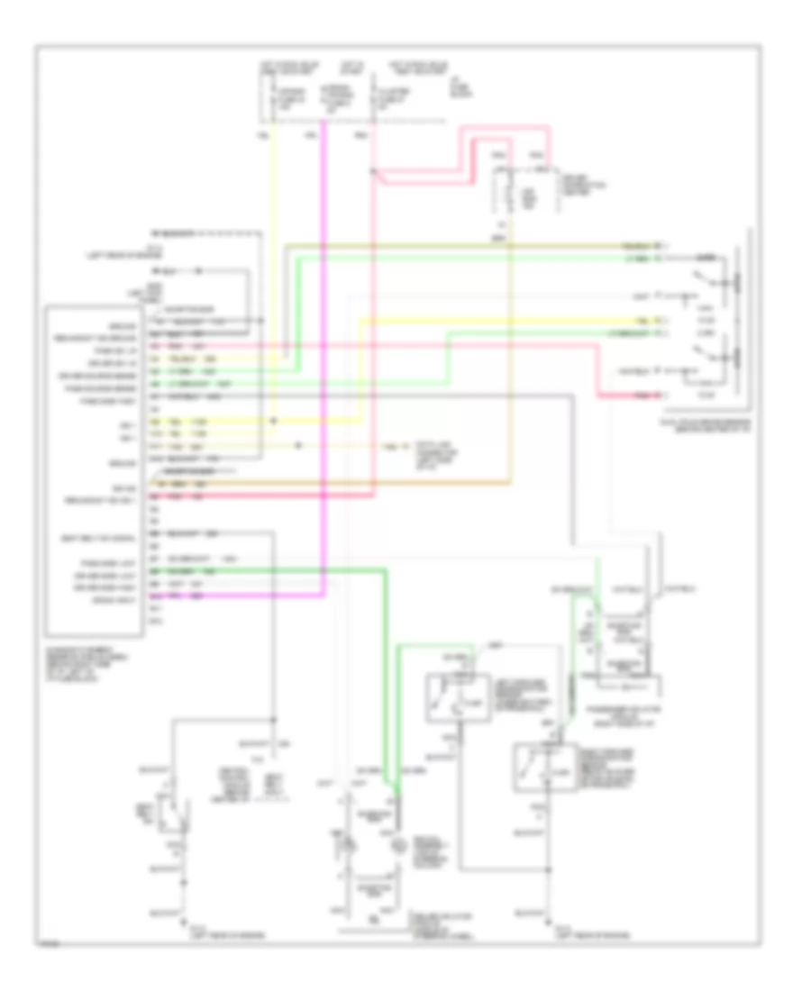
Supplemental Restraint Wiring Diagram for Chevrolet Corvette 1996
List of elements for Supplemental Restraint Wiring Diagram for Chevrolet Corvette 1996:
- 10.2k
- 2.49k
- 8.45k
- A10
- A11
- A12
- Air bag fuse 34 15a
- Air bag ind
- B10
- B11
- B12
- Central control module (behind center i/p)
- Cluster fuse 27 5a
- Crank air bag fuse 9 5a
- Crank input
- Data link connector (left side of i/p)
- Diagnostic energy reserve module (derm) (behind right side of i/p, left of i/p fuse block)
- Driver 36v lr
- Driver inflator module (middle of steering wheel)
- Driver information center
- Driver side "high"
- Driver side "low"
- Driver source sense
- Dual pole arming sensor (behind center of i/p)
- F10
- G114 (left rear of engine)
- G114 (left rear of engine)
- G200 (left kick panel)
- Ground
- Hot in run, bulb test or start
- Hot in start
- I/p fuse block
- Ign 1
- Left forward discriminating sensor (under battery, on frame rail)
- Nca
- Pass 36v lr
- Pass side "high"
- Pass side "low"
- Pass source sense
- Passenger inflator module (right side of i/p)
- Pnk
- Redundant ind ground
- Redundant ind ign 1
- Right forward discriminating sensor (below blower motor housing, on frame rail)
- Seat belt input
- Seat belt sw
- Seat belt sw signal
- Shorting bar
- Sir coil assembly (top of steering column)
- Sir ind
- Tan
 English