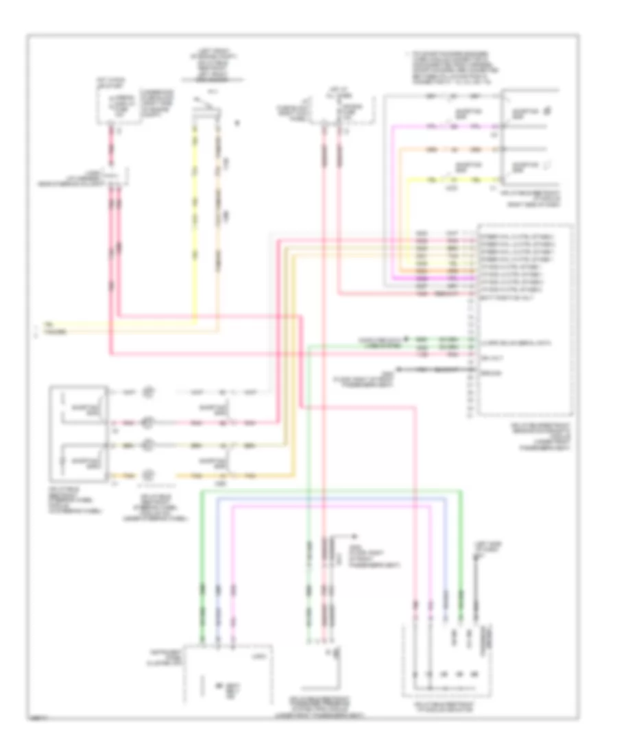
SUPPLEMENTAL RESTRAINTS
Supplemental Restraints Wiring Diagram (1 of 2) for Chevrolet Impala LTZ 2012

List of elements for Supplemental Restraints Wiring Diagram (1 of 2) for Chevrolet Impala LTZ 2012:
- (driver's door) inflatable restraint left side impact sensor (sis)
- (front passenger's door) inflatable restraint right side impact sensor (sis)
- (left side of driver's seat back) inflatable restraint left side impact module
- (right "c" pillar)
- (right front
- (right side of front passenger's seat back) inflatable restraint right side impact module
- B12
- C11
- C12
- Driver seat belt buckle
- Driver seat belt pretensioner
- Driver seat belt retractor pretensioner
- Driver seat belt switch
- Inflatable restraint left roof rail module
- Inflatable restraint right front end sensor
- Inflatable restraint right roof rail module
- Inflatable restraint sensing & diagnostic module (under front passenger's seat)
- Left roof rail mod high
- Left roof rail mod low
- Lf end sensor sig
- Lf side impact mod high
- Lf side impact mod low
- Lh pretensioner high
- Lh pretensioner low
- Lh seat belt sw
- Lh seat belt sw low ref
- Lh side impact sensing mod
- Low ref
- Low ref rf end sensor sig
- Nca
- Of engine compt)
- Passenger seat belt buckle
- Passenger seat belt pretensioner
- Passenger seat belt retractor pretensioner
- Passenger seat belt switch
- Pin shorting bars engaged
- Pnk
- Red
- Rf side impact mod high
- Rf side impact mod low
- Rh pretensioner high
- Rh pretensioner low
- Rh roof rail mod high ctrl
- Rh roof rail mod low ctrl
- Rh seat belt sw sig
- Rh side impact sensing mod
- Shorting bar
- Tan
- When module connector is disconnected from harness: (shorting bars are connected between following pins in connector x2: 9-10, 11-12, 17-18, 37-38, 39-40, 53-54)
- X120
- X200
- X311
- X313
- X315
- X316
- X500
- X600
Supplemental Restraints Wiring Diagram (2 of 2) for Chevrolet Impala LTZ 2012
List of elements for Supplemental Restraints Wiring Diagram (2 of 2) for Chevrolet Impala LTZ 2012:
- (floor, right of front passenger's seat)
- (i/p harness, near steering column)
- (left front of engine compt)
- (left side
- Air bag
- Air bag fuse 10a
- Airbag/ display fuse 10a
- B11
- B12
- Batt positive volt
- Computer data lines system
- G201
- G302
- G302 (floor, right of front passenger's seat)
- Gnd
- Ground
- Hot at all times
- Hot in run or start
- I/p fuse block (right kick panel)
- I/p mod hi ctrl stage 1
- I/p mod hi ctrl stage 2
- I/p mod lo ctrl stage 1
- I/p mod lo ctrl stage 2
- Ign volt
- Inflatable restraint i/p module (right side of dash)
- Inflatable restraint i/p module indicator
- Inflatable restraint left front end sensor
- Inflatable restraint passenger presence system (pps) module (under front passenger's seat)
- Inflatable restraint sensing & diagnostic module (under front passenger's seat)
- Inflatable restraint steering wheel module (in steering wheel)
- Inflatable restraint steering wheel module coil (under steering wheel)
- Instrument panel cluster (ipc)
- Jx206
- Lo spd gmlan serial data
- Logic
- Of dash)
- Off ind
- On ind
- Passenger
- Pin shorting bars engaged
- Pnk
- Seat belt ind
- Shorting bar
- Steer whl hi ctrl stage 1
- Steer whl hi ctrl stage 2
- Steer whl lo ctrl stage 1
- Steer whl lo ctrl stage 2
- Tan
- Underhood fuse block (right side of engine compt)
- When module connector is disconnected from harness: (shorting bars are connected between following pins in connector x1: 1-2, 3-4, 5-6, 7-8)
- X120
- X200
- X250
- X278
- X313