SUPPLEMENTAL RESTRAINTS
Supplemental Restraints Wiring Diagram (1 of 2) for Chevrolet Malibu LT 2006

List of elements for Supplemental Restraints Wiring Diagram (1 of 2) for Chevrolet Malibu LT 2006:
- A pnk
- Air bag (batt) fuse 10a
- Air bag (ign) fuse 10a
- Body control module (bcm) (below right side of dash, near blower motor)
- Case ground
- Computer data lines system
- D11
- G304 (right kick panel)
- Ground
- High control
- Hot at all times
- Hot in run or start
- Ignition 1
- Inflatable restraint sensing & diagnostic module (sdm) (under center console, under carpet)
- Left front inflatable restraint seat belt pretensioner (bottom of left "b" pillar)
- Left inflatable restraint front end sensor (left front of engine compt)
- Left inflatable restraint roof rail module (on upper left "c" pillar)
- Left inflatable restraint side impact sensor (sis) (behind door panel)
- Low control
- Low ref
- Nca
- Pnk
- Right front inflatable restraint seat belt pretensioner (bottom of right "b" pillar)
- Right inflatable restraint front end sensor (right front of engine compt)
- Right inflatable restraint roof rail module (on upper right "c" pillar)
- Right inflatable restraint side impact sensor (sis) (behind door panel)
- Seat belt switch
- Serial data
- Shorting bar
- Signal
- Tan
- Voltage
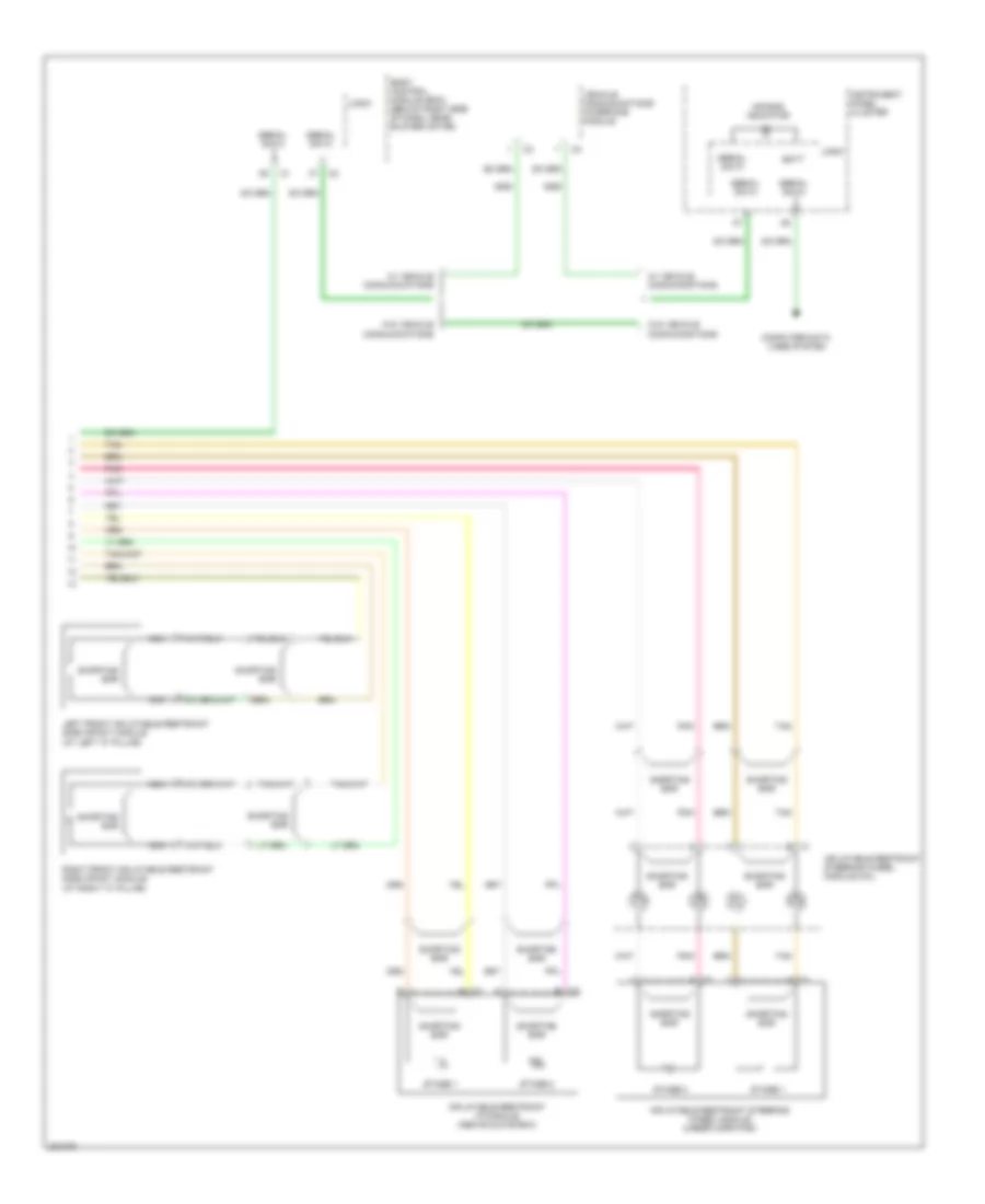
Supplemental Restraints Wiring Diagram (2 of 2) for Chevrolet Malibu LT 2006
List of elements for Supplemental Restraints Wiring Diagram (2 of 2) for Chevrolet Malibu LT 2006:
- A c1
- Air bag indicator
- B c2
- Batt
- Body control module (bcm) (below right side of dash, near blower motor)
- Computer data lines system
- Inflatable restraint i/p module (above glove box)
- Inflatable restraint steering wheel module (under horn pad)
- Inflatable restraint steering wheel module coil
- Instrument panel cluster
- Left front inflatable restraint side impact module (at left "c" pillar)
- Logic
- Nca
- Pnk
- Right front inflatable restraint side impact module (at right "c" pillar)
- Serial data
- Shorting bar
- Stage 1
- Stage 2
- Tan
- Vehicle communications interface module
- W/ vehicle communications
- W/o vehicle communications