SUPPLEMENTAL RESTRAINTS
Supplemental Restraints Wiring Diagram (1 of 3) for Chevrolet Malibu LT 2014

List of elements for Supplemental Restraints Wiring Diagram (1 of 3) for Chevrolet Malibu LT 2014:
- (center of steering wheel) steering wheel air bag
- (not used)
- Air bag ind
- Battery positive voltage
- Bdy rc ign fuse 10a
- Belt ind passenger seat
- Computer data lines system
- Driver information center display
- Driver knee air bag (lower left of dash)
- Drv knee mod hi ctrl
- Drv knee mod lo ctrl
- Fuse 5a
- G302 (right kick panel)
- G303 (below left front seat on floor)
- G403 (left rear wheel well in luggage compt)
- Ground
- Hot at all times
- Hot w/ ignition main relay energized
- Inflatable restraint sensing & diagnostic module (sdm) (forward of transmission shift lever on floor)
- Instrument cluster
- Instrument panel fuse block (left side of dash)
- J136
- J204
- J302
- J309
- Left front impact sensor (near left radiator support)
- Lo spd
- Lo spd gmlan serial data
- Logic
- Nca
- Off ind air bag
- On ind air bag
- Pass air bag off ind ctrl
- Pass air bag on ind ctrl
- Pass ip mod stage 1 hi ctrl
- Pass ip mod stage 1 lo ctrl
- Pass ip mod stage 2 hi ctrl
- Pass ip mod stage 2 lo ctrl
- Pass knee mod hi ctrl
- Pass knee mod lo ctrl
- Pass seat belt ind
- Passenger air bag disabled indicator
- Passenger instrument panel air bag
- Passenger knee air bag (lower right of dash)
- Passenger presence module (passenger seat between cover & cushion)
- Passenger presence sensor (between passenger seat cover and cushion)
- Pin shorting bars engaged when module connector is disconnected from harness: (shorting bars are connected between following pins in connector x1: 1-2, 3-4, 5-6, 7-8, 21-22 & 23-24)
- Pnk
- Red
- Right front impact sensor (near right radiator support)
- Run/crank ignition 1 voltage
- Seat belt ind
- Shorting bar
- Steering wheel air bag coil
- Steering wheel mod stage 1 hi ctrl
- Steering wheel mod stage 1 lo ctrl
- Steering wheel mod stage 2 hi ctrl
- Steering wheel mod stage 2 lo ctrl
- Tan
- Underhood fuse block (left side of battery)
- X150
- X205
- X210
- X320
- X400
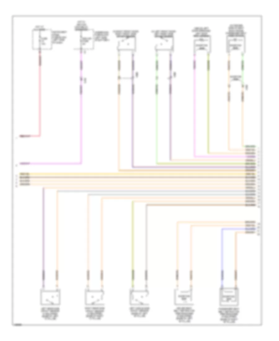
Supplemental Restraints Wiring Diagram (2 of 3) for Chevrolet Malibu LT 2014
List of elements for Supplemental Restraints Wiring Diagram (2 of 3) for Chevrolet Malibu LT 2014:
- (above left door openings) left roof rail air bag
- (in left front door) left front side impact sensor
- (in right front door) right front side impact sensor
- (outboard side of seat back frame) passenger seat side air bag
- Driver seat belt retractor pretensioner (if equipped) (base of left "b" pillar)
- Fuse 10a
- Hot at all times
- Hot w/ ignition main relay energized
- Instrument panel fuse block (left side of dash)
- Left middle side impact sensor (base of left "b" pillar)
- Left rear side impact sensor (if equipped) (base of left "c" pillar)
- Passenger seat belt retractor pretensioner (if equipped) (base of right "b" pillar)
- Right rear side impact sensor (if equipped) (base of right "c" pillar)
- Sdm ign fuse 5a
- Shorting bar
- Underhood fuse block (left side of battery)
- X210
- X320
- X500
- X600
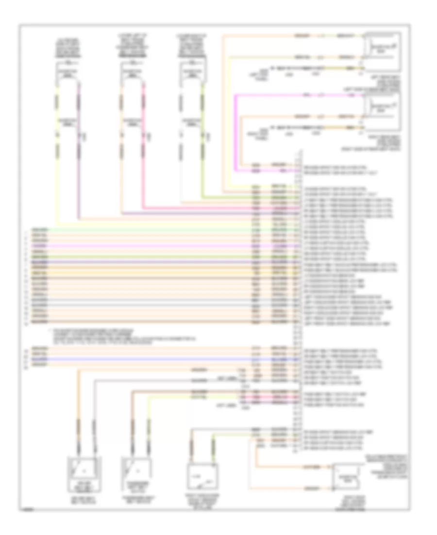
Supplemental Restraints Wiring Diagram (3 of 3) for Chevrolet Malibu LT 2014
List of elements for Supplemental Restraints Wiring Diagram (3 of 3) for Chevrolet Malibu LT 2014:
- (lower left of seat frame) (if equipped) passenger seat belt anchor pretensioner
- (lower right of seat frame) (if equipped) driver seat belt anchor pretensioner
- (not used)
- (outboard side of seat back frame) driver seat side air bag
- Dr seat belt pretensioner high ctrl
- Dr seat belt pretensioner low ctrl
- Dr seat belt switch low ref
- Dr seat belt switch sig
- Dr seat position switch sig
- Dr side impact module high ctrl
- Dr side impact module low ctrl
- Driver seat belt buckle
- Driver seat belt switch
- G302 (right kick panel)
- G305 (left kick panel)
- Inflatable restraint sensing & diagnostic module (sdm) (forward of transmission shift lever on floor)
- J302
- J305
- Left front side impact sensing mod low ref
- Left front side impact sensing mod sig
- Left middle side impact sensing mod low ref
- Left middle side impact sensing mod sig
- Left rear seat side air bag (if equipped) (left side of rear seat back)
- Lf discriminating sens low ref
- Lf discriminating sens sig
- Lf head curtain module high ctrl
- Lf head curtain module low ctrl
- Lf seat belt pretensioner stage 2 high ctrl
- Lf seat belt pretensioner stage 2 low ctrl
- Lf side impact module high ctrl
- Lf side impact module low ctrl
- Lr side impact sir inflator ctrl
- Lr side impact sir inflator sply volt
- Nca
- Pass seat belt buckle pretensioner high ctrl
- Pass seat belt buckle pretensioner low ctrl
- Pass seat belt pretensioner high ctrl
- Pass seat belt pretensioner low ctrl
- Pass seat belt switch low ref
- Pass seat belt switch sig
- Pass seat position switch sig
- Passenger seat belt buckle
- Passenger seat belt switch
- Pin shorting bars engaged when module connect is disconnected from harness: (shorting bars are connected between following pins in connector x2: 3-4, 7-8, 9-10, 11-12, 13-14, 15-16, 17-18, 37-38, 39-40 & 53-54)
- Rf discriminating sens low ref
- Rf discriminating sens sig
- Rf head curtain mod high ctrl
- Rf head curtain mod low ctrl
- Rf seat belt pretensioner stage 2 high ctrl
- Rf seat belt pretensioner stage 2 low ctrl
- Rf side impact module high ctrl
- Rf side impact module low ctrl
- Rf side impact sensing mod low ref
- Rf side impact sensing mod sig
- Right middle side impact sensing mod low ref
- Right middle side impact sensing mod sig
- Right middle side impact sensor (base of right "b" pillar)
- Right rear seat side air bag (if equipped) (right side of rear seat back)
- Right roof rail air bag (above right door openings)
- Rr side impact sir inflator ctrl
- Rr side impact sir inflator sply volt
- Shorting bar
- X310
- X320
- X321
- X322