SUPPLEMENTAL RESTRAINTS
Supplemental Restraints Wiring Diagram (1 of 2) for Chevrolet Malibu Maxx SS 2006

List of elements for Supplemental Restraints Wiring Diagram (1 of 2) for Chevrolet Malibu Maxx SS 2006:
- A pnk
- Air bag (batt) fuse 10a
- Air bag (ign) fuse 10a
- Body control module (bcm) (below right side of dash, near blower motor)
- Case ground
- Computer data lines system
- D11
- G304 (right kick panel)
- Ground
- High control
- Hot at all times
- Hot in run or start
- Ignition 1
- Inflatable restraint sensing & diagnostic module (sdm) (under center console, under carpet)
- Left front inflatable restraint seat belt pretensioner (bottom of left "b" pillar)
- Left inflatable restraint front end sensor (left front of engine compt)
- Left inflatable restraint roof rail module (on upper left "c" pillar)
- Left inflatable restraint side impact sensor (sis) (behind door panel)
- Low control
- Low ref
- Nca
- Pnk
- Right front inflatable restraint seat belt pretensioner (bottom of right "b" pillar)
- Right inflatable restraint front end sensor (right front of engine compt)
- Right inflatable restraint roof rail module (on upper right "c" pillar)
- Right inflatable restraint side impact sensor (sis) (behind door panel)
- Seat belt switch
- Serial data
- Shorting bar
- Signal
- Tan
- Voltage
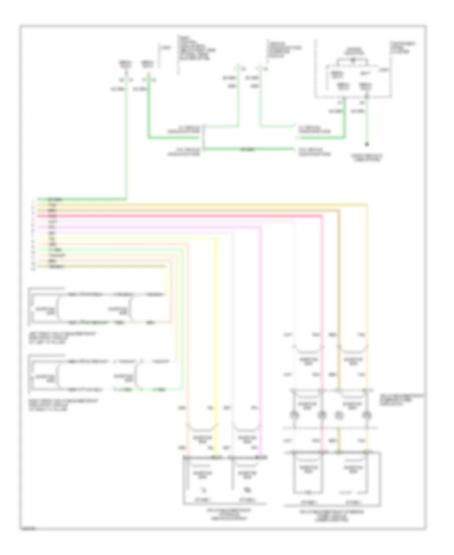
Supplemental Restraints Wiring Diagram (2 of 2) for Chevrolet Malibu Maxx SS 2006
List of elements for Supplemental Restraints Wiring Diagram (2 of 2) for Chevrolet Malibu Maxx SS 2006:
- A c1
- Air bag indicator
- B c2
- Batt
- Body control module (bcm) (below right side of dash, near blower motor)
- Computer data lines system
- Inflatable restraint i/p module (above glove box)
- Inflatable restraint steering wheel module (under horn pad)
- Inflatable restraint steering wheel module coil
- Instrument panel cluster
- Left front inflatable restraint side impact module (at left "c" pillar)
- Logic
- Nca
- Pnk
- Right front inflatable restraint side impact module (at right "c" pillar)
- Serial data
- Shorting bar
- Stage 1
- Stage 2
- Tan
- Vehicle communications interface module
- W/ vehicle communications
- W/o vehicle communications