
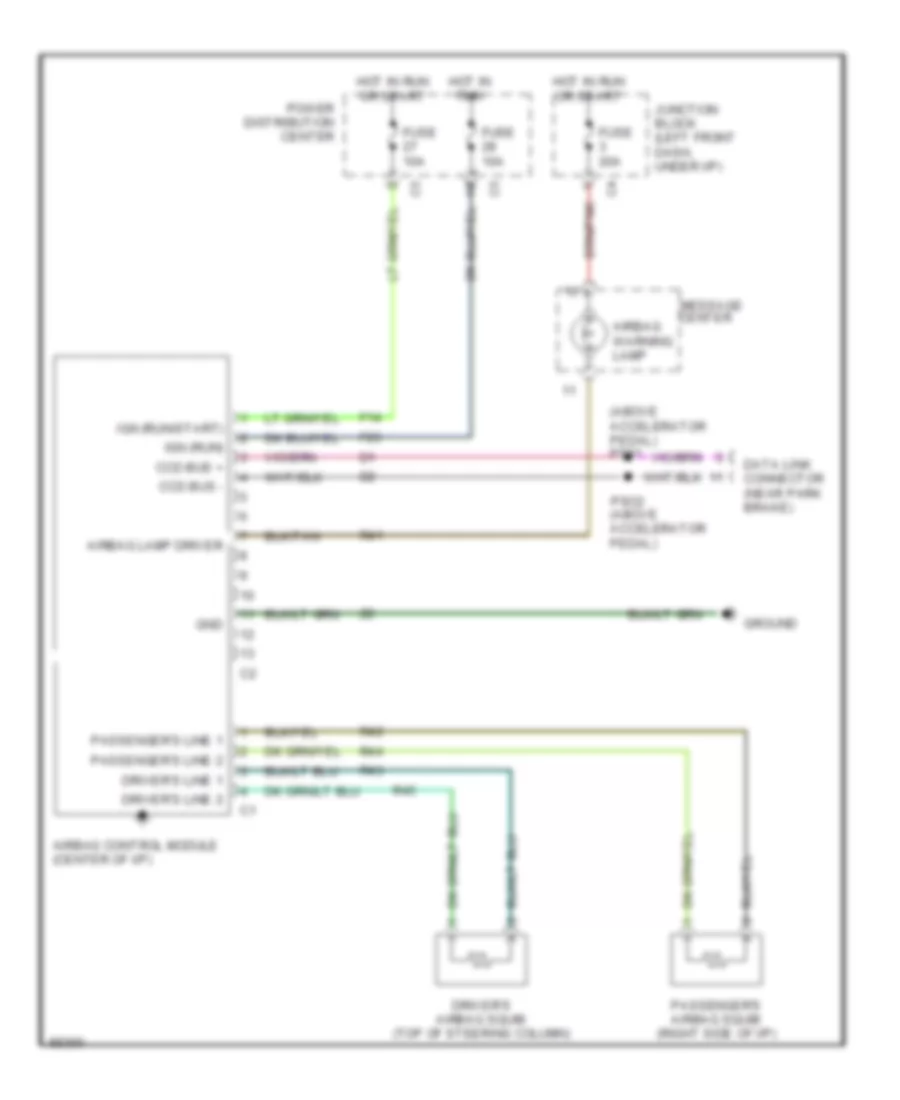
SUPPLEMENTAL RESTRAINTS
Supplemental Restraint Wiring Diagram for Chrysler Town & Country LX 1997
List of elements for Supplemental Restraint Wiring Diagram for Chrysler Town & Country LX 1997:
AIR CONDITIONINGANTI-THEFTANTI-LOCK BRAKESBODY COMPUTERENGINE PERFORMANCECOMPUTER DATA LINESEXTERIOR LIGHTSCRUISE CONTROLGROUND DISTRIBUTIONCOOLING FANDEFOGGERSHORNINTERIOR LIGHTSINSTRUMENT CLUSTERHEADLIGHTSPOWER DISTRIBUTIONPOWER DOOR LOCKSPOWER MIRRORSMEMORY SYSTEMSPOWER SEATSRADIOPOWER WINDOWSSUPPLEMENTAL RESTRAINTSSTARTING/CHARGINGTRANSMISSIONWARNING SYSTEMSWIPER/WASHER