
SUPPLEMENTAL RESTRAINTS
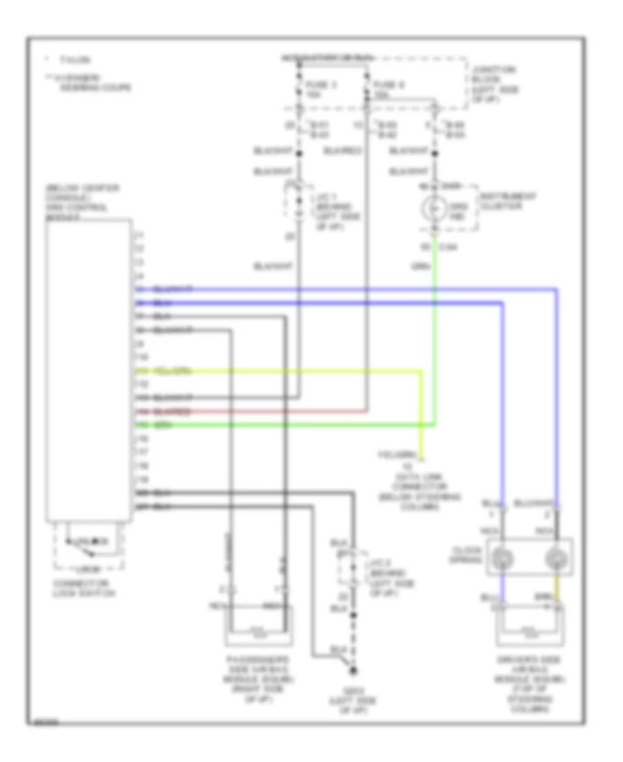
Supplemental Restraint Wiring Diagram for Dodge Avenger 1997
List of elements for Supplemental Restraint Wiring Diagram for Dodge Avenger 1997:
ANTI-LOCK BRAKESANTI-THEFTAIR CONDITIONINGBODY COMPUTERCOMPUTER DATA LINESCRUISE CONTROLEXTERIOR LIGHTSENGINE PERFORMANCECOOLING FANDEFOGGERSGROUND DISTRIBUTIONHEADLIGHTSINTERIOR LIGHTSINSTRUMENT CLUSTERPOWER TOP/SUNROOFPOWER DOOR LOCKSPOWER WINDOWSPOWER MIRRORSPOWER SEATSPOWER DISTRIBUTIONHORNSUPPLEMENTAL RESTRAINTSRADIOTRANSMISSIONSTARTING/CHARGINGWARNING SYSTEMSWIPER/WASHER