AUTOMOTIVE ELECTRICIANS PORTAL

SUPPLEMENTAL RESTRAINTS – Dodge Dakota 1997 – SYSTEM WIRING DIAGRAMS

SUPPLEMENTAL RESTRAINTS

Supplemental Restraint Wiring Diagram for Dodge Dakota 1997

Supplemental Restraint Wiring Diagram for Dodge Dakota 1997 https://portal-diagnostov.com/license.html
https://portal-diagnostov.com/license.html Automotive Electricians Portal FZCO Automotive Electricians Portal FZCO
Get Access az összes kapcsolási rajz autóDownload PDF file

List of elements for Supplemental Restraint Wiring Diagram for Dodge Dakota 1997:
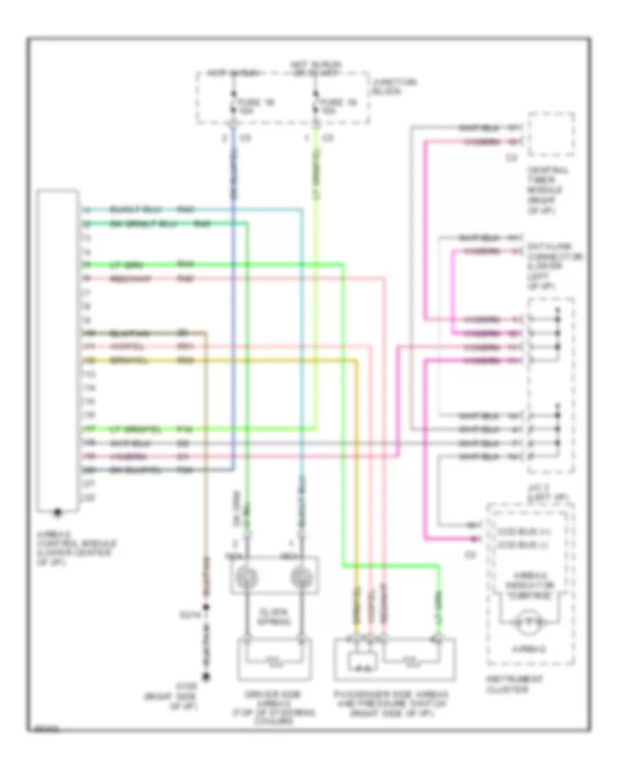
  • Airbag
  • Airbag control module (lower center of i/p)
  • Airbag indicator control
  • Ccd bus (+)
  • Ccd bus (-)
  • Central timer module (right of i/p)
  • Clock spring
  • Datalink connector (lower left of i/p)
  • Driver side airbag (top of steering coulmn)
  • F14
  • F24
  • Fuse 18 10a
  • Fuse 19 10a
  • G120 (right side of i/p)
  • Hot in run
  • Hot in run or start
  • Instrument cluster
  • J/c 3 (left i/p)
  • Junction block
  • Nca
  • P.s.
  • Passenger side airbag and pressure switch (right side of i/p)
  • R42
  • R43
  • R44
  • R45
  • R50
  • R51
  • S214