
SUPPLEMENTAL RESTRAINTS
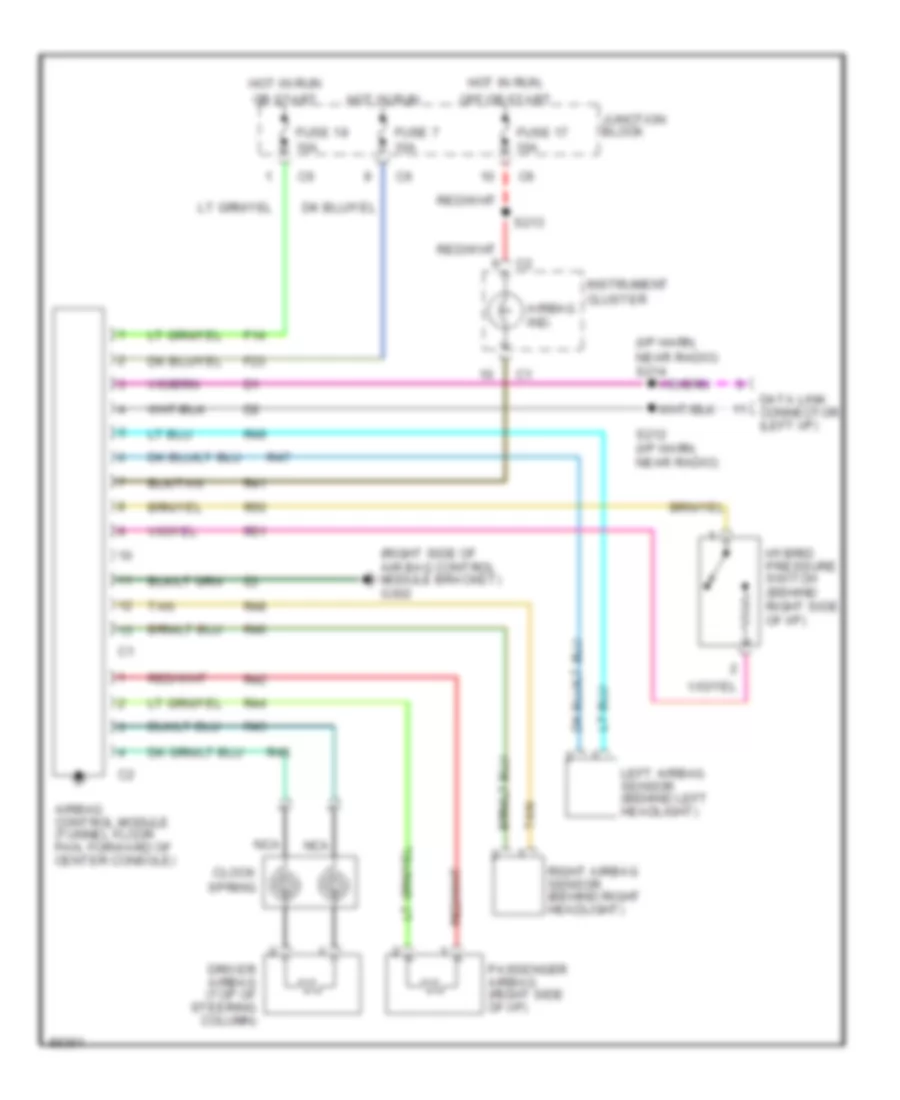
Supplemental Restraint Wiring Diagram for Dodge Intrepid 1997
List of elements for Supplemental Restraint Wiring Diagram for Dodge Intrepid 1997:
ANTI-LOCK BRAKESANTI-THEFTAIR CONDITIONINGCOOLING FANCOMPUTER DATA LINESCRUISE CONTROLBODY COMPUTERDEFOGGERSHEADLIGHTSENGINE PERFORMANCEGROUND DISTRIBUTIONHORNEXTERIOR LIGHTSINSTRUMENT CLUSTERPOWER ANTENNAELECTRONIC POWER STEERINGPOWER DISTRIBUTIONPOWER DOOR LOCKSINTERIOR LIGHTSPOWER SEATSPOWER MIRRORSPOWER WINDOWSSTARTING/CHARGINGPOWER TOP/SUNROOFTRUNK, TAILGATE, FUEL DOORWARNING SYSTEMSRADIOTRANSMISSIONSUPPLEMENTAL RESTRAINTSWIPER/WASHER