
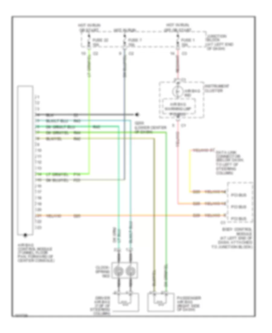
SUPPLEMENTAL RESTRAINTS
Supplemental Restraint Wiring Diagram for Dodge Intrepid ES 1998
List of elements for Supplemental Restraint Wiring Diagram for Dodge Intrepid ES 1998:
AIR CONDITIONINGANTI-THEFTDEFOGGERSBODY COMPUTERCOOLING FANCRUISE CONTROLCOMPUTER DATA LINESANTI-LOCK BRAKESEXTERIOR LIGHTSELECTRONIC POWER STEERINGHEADLIGHTSHORNGROUND DISTRIBUTIONENGINE PERFORMANCEPOWER DISTRIBUTIONPOWER DOOR LOCKSINSTRUMENT CLUSTERINTERIOR LIGHTSPOWER MIRRORSSTARTING/CHARGINGRADIOPOWER TOP/SUNROOFPOWER SEATSPOWER WINDOWSSUPPLEMENTAL RESTRAINTSTRUNK, TAILGATE, FUEL DOORTRANSMISSIONWARNING SYSTEMSWIPER/WASHER