
SUPPLEMENTAL RESTRAINTS
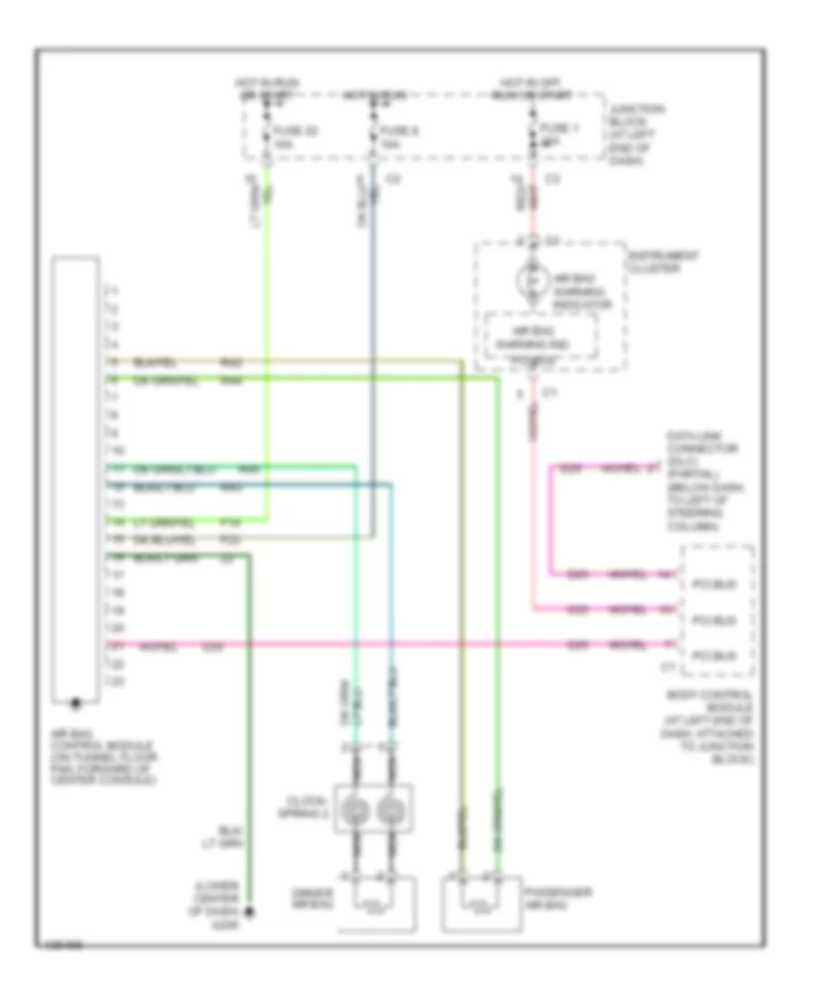
Supplemental Restraint Wiring Diagram for Dodge Intrepid R/T 2000
List of elements for Supplemental Restraint Wiring Diagram for Dodge Intrepid R/T 2000:
ANTI-LOCK BRAKESANTI-THEFTAIR CONDITIONINGBODY COMPUTERCOOLING FANDEFOGGERSELECTRONIC POWER STEERINGCRUISE CONTROLCOMPUTER DATA LINESHORNGROUND DISTRIBUTIONEXTERIOR LIGHTSPOWER DOOR LOCKSENGINE PERFORMANCEINSTRUMENT CLUSTERPOWER WINDOWSHEADLIGHTSPOWER MIRRORSINTERIOR LIGHTSRADIOPOWER SEATSPOWER DISTRIBUTIONSHIFT INTERLOCKSPOWER TOP/SUNROOFTRUNK, TAILGATE, FUEL DOORSUPPLEMENTAL RESTRAINTSSTARTING/CHARGINGTRANSMISSIONWARNING SYSTEMSWIPER/WASHER