SUPPLEMENTAL RESTRAINTS
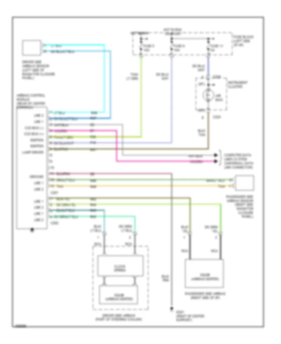
Supplemental Restraint Wiring Diagram for Dodge Neon High Line 1995
List of elements for Supplemental Restraint Wiring Diagram for Dodge Neon High Line 1995:
- (rt)
- Air bag
- Airbag control module (rear of center console)
- C201
- C202
- C224
- Ccd bus (+)
- Ccd bus (-)
- Clock spring
- Computer data lines system (universal data link connector)
- Driver side airbag (part of steering coulmn)
- Driver side airbag sensor (left side of radiator closure panel)
- F15
- F25
- Fuse 11 5a
- Fuse 5 10a
- Fuse 9 10a
- Fuse block (left side of i/p)
- G201 (right i/p center support)
- Ground
- Hot in run
- Hot in run or start
- Ignition
- Instrument cluster
- Lamp driver
- Line 1
- Line 2
- Nca
- Passenger side airbag (right side of i/p)
- Passenger side airbag sensor (right side radiator closure panel)
- R41
- R42
- R43
- R44
- R45
- R46
- R47
- R48
- R49
- Squib (airbag igniter)
- Tan
 English