SUPPLEMENTAL RESTRAINTS
Supplemental Restraint Wiring Diagram for Dodge Neon High Line 2000
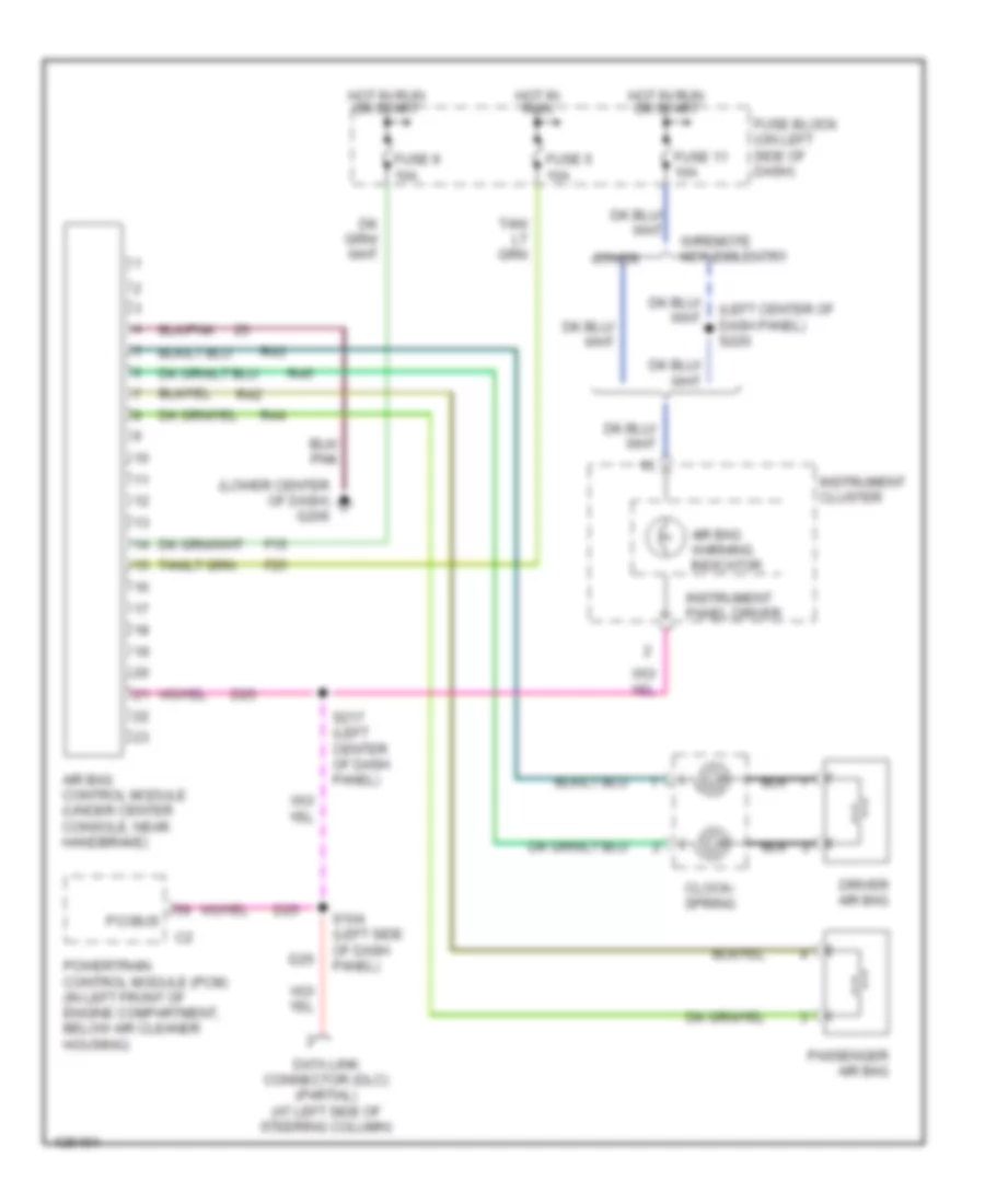
List of elements for Supplemental Restraint Wiring Diagram for Dodge Neon High Line 2000:
- (left center of dash panel) s220
- (lower center of dash) g206
- Air bag control module (under center console, near handbrake)
- Air bag warning indicator
- Clock- spring
- D25
- Data link connector (dlc) (partial) (at left side of steering column)
- Driver air bag
- F15
- F25
- Fuse 11 10a
- Fuse 5 10a
- Fuse 9 10a
- Fuse block (on left side of dash)
- Hot in run
- Hot in run or start
- Instrument cluster
- Instrument panel driver
- Other
- Passenger air bag
- Pci bus
- Powertrain control module (pcm) (in left front of engine compartment, below air cleaner housing)
- R42
- R43
- R44
- R45
- S104 (left side of dash panel)
- S217 (left center of dash panel)
- W/remote keyless entry
 English