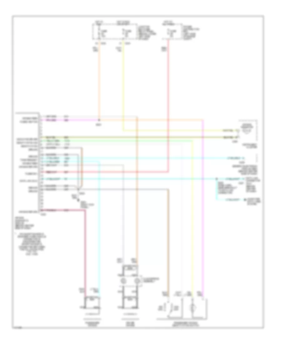
SUPPLEMENTAL RESTRAINTS
Supplemental Restraints Wiring Diagram for Ford Cab & Chassis F350 Super Duty 1999
List of elements for Supplemental Restraints Wiring Diagram for Ford Cab & Chassis F350 Super Duty 1999:
- (behind center of dash)
- Air bag diagnostic module (behind center side of dash)
- Air bag feed
- Air bag indicator
- Air bag return
- C223
- C227
- C239
- C242
- C243
- C250
- Clockspring assembly
- Computer data lines system
- Connector (dlc)
- Data link
- Data link (dlc)
- Deactivation
- Deactivation ind
- Driver air bag
- Fuse 10a
- Fuse 5a
- Fused b(+)
- Fused ignition
- G203 (right kick panel)
- Generic electronic module (gem) (behind center side of dash)
- Ground
- Hot at all times
- Hot in run
- Hot in run or start
- Indicator driver
- Instrument cluster
- Junction box fuse/ relay panel (behind lower left side of dash)
- Nca
- Ohm
- Passenger air bag
- Passenger air bag deactivation switch
- Pin shorting bar is engaged when module connector is disconnected (shorting bar is connected between the following pins: 1-15, 7-21, 8-22, 14-28)
- Power distribution box (left side of engine compt)
- S202
- S203
- S225 (dash harn, near breakout to data link connector)
- Shorting bar
- Tone request
 English