SUPPLEMENTAL RESTRAINTS
Supplemental Restraint Wiring Diagram for Ford Club Wagon E150 1995
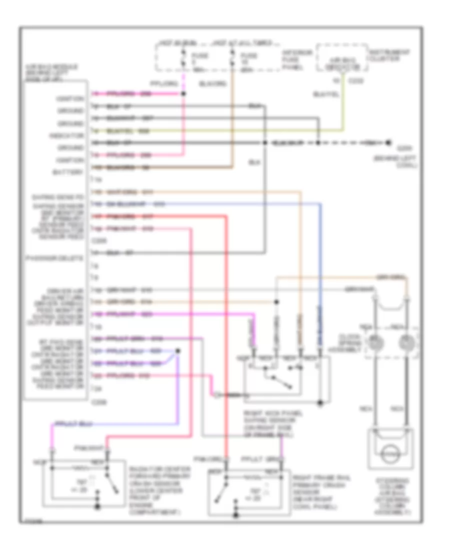
List of elements for Supplemental Restraint Wiring Diagram for Ford Club Wagon E150 1995:
- (behind left cowl)
- +/- 20
- Air bag indicator
- Air bag module (behind left side of i/p)
- Battery
- C208
- C209
- C232
- Clock- spring assembly
- Driver air bag return driver airbag feed monitor safing sensor output monitor
- Fuse 15a
- Fuse 20a
- G200
- Ground
- Hot at all times
- Hot in run
- Ignition
- Indicator
- Instrument cluster
- Interior fuse panel
- Nca
- Passngr delete
- Radiator center forward primary crash sensor (lower center front of engine compartment)
- Right frame rail primary crash sensor (near right cowl panel)
- Right kick panel safing sensor (on right side of frame rail)
- Rt fwd sens grd monitor cntr radiator grd monitor cntr radiator grd monitor safing sensor feed monitor
- Safing sens fd
- Safing sensor gnd monitor rt (primary) sensor feed cntr radiator sensor feed
- Steering column air bag (steering column assembly)
 English