SUPPLEMENTAL RESTRAINTS
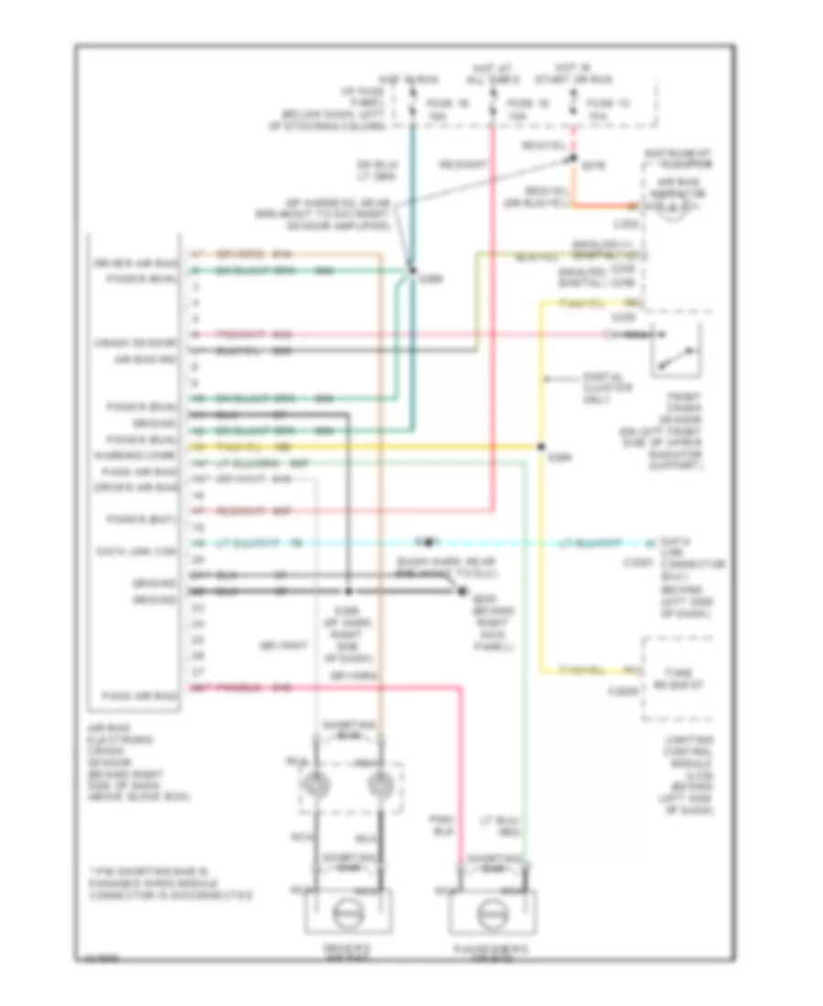
Supplemental Restraint Wiring Diagram for Ford Crown Victoria Police Interceptor 1998
List of elements for Supplemental Restraint Wiring Diagram for Ford Crown Victoria Police Interceptor 1998:
- (analog) (digital)
- (behind left side of dash)
- (behind right kick panel)
- (dash harn, near breakout to dlc)
- (i/p harn, right side of dash)
- (i/p harness, near breakout to day/night sensor amplifier)
- * pin shorting bar is engaged when module connector is disconnected
- Air bag electronic crash sensor (behind right side of dash, above glove box)
- Air bag ind
- Air bag indicator
- C2026
- C250
- C255
- C256
- Crash sensor
- Data link c2021 connector (dlc)
- Data link con
- Digital cluster only
- Driver air bag
- Driver's air bag
- Front crash sensor (on left front side of upper radiator support)
- Fuse 10 10a
- Fuse 13 15a
- Fuse 18 10a
- G203
- Ground
- Hot at all times
- Hot in run i/p fuse panel (below dash, left of steering column)
- Hot in start or run
- Instrument cluster
- Lighting control module (lcm) (behind left side of dash)
- Nca
- Pass air bag
- Passenger's air bag
- Power (bat)
- Power (run)
- S209
- S269
- S271
- S276
- S284
- Shorting bar
- Tone request
- Warning chime
 English