SUPPLEMENTAL RESTRAINTS
Supplemental Restraints Wiring Diagram (1 of 2) for Ford Crown Victoria S 2005

List of elements for Supplemental Restraints Wiring Diagram (1 of 2) for Ford Crown Victoria S 2005:
- (behind right kick panel)
- (in body main harness, near breakout to restraints control module)
- (in main body wiring harness, near breakout to g200)
- (in main body wiring harness, near breakout to instrument cluster) s208
- C175b
- C310a
- C310b
- Central junction box (cjb) (below dash, left of steering column)
- Computer data lines system
- Driver safety belt retractor pretensioner (left side of vehicle floor)
- Driver seat belt buckle sensor (in driver's seat)
- Driver seat track position sensor (below driver seat)
- Fuse 10a
- G201
- G201 (behind right kick panel)
- Gnd
- Ground
- Hot in run or start
- Hs can +
- Hs can -
- Iso
- Left side impact sensor (base of left "b" pillar)
- Nca
- Pad ind
- Passenger air bag module
- Passenger safety belt retractor pretensioner (right side of vehicle floor)
- Pin shorting bars engaged when module connector is disconnected from harness shorting bars are connected between pins: 1-2, 3-4, 5-6, 13-14, 15-16 conn. c310a 1-2, 21-22 conn. c310b
- Powertrain control module (pcm) (left rear side of engine compt)
- Pwr
- Rdi
- Red
- Restraints control module (below center of dash)
- Right front impact severity sensor (on front right of engine compartment)
- Right side impact sensor (base of right "b" pillar)
- Ril
- S213 (in main body wiring harness, near breakout to c237)
- S217
- S301 (in power seats harness, in breakout to c311)
- S305
- Shorting bar
- Sig rtn
- Stage 1
- Stage 2
- Tone req
- Vpwr
- Vref
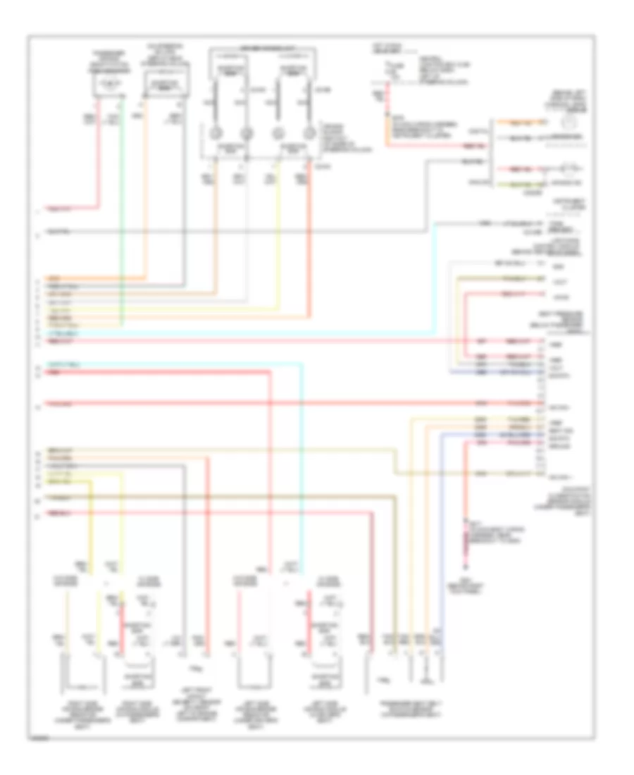
Supplemental Restraints Wiring Diagram (2 of 2) for Ford Crown Victoria S 2005
List of elements for Supplemental Restraints Wiring Diagram (2 of 2) for Ford Crown Victoria S 2005:
- (behind left side of dash) warning lamps module
- (on steering column) deployable steering column
- Air bag ind
- Air bag sliding contact (at base of steering column)
- Analog
- C2145b
- C216a
- C216b
- C218a
- C2220b
- Central junction box (cjb) (below dash, left of steering column)
- Digital
- Driver air bag unit
- Fuse 10a
- G201 (behind right kick panel)
- Gnd
- Ground
- Hot in run or start
- Hs can +
- Hs can -
- Instrument cluster
- Left front impact severity sensor (on front left of engine compartment)
- Left side air bag bridge resistor (under driver's seat)
- Left side air bag module (in driver's seat)
- Lightining control module (behind center of dash)
- Nca
- Occupant classification sensor module (under passenger's seat)
- Passenger air bag deactivation (pad) indicator
- Passenger seat belt buckle sensor (in passenger's seat)
- Red
- Right side air bag bridge resistor (under passenger's seat)
- Right side air bag module (in passenger's seat)
- S217 (in main body wiring harness, near breakout to g200)
- S276 (in main wiring harness, near breakout to instrument cluster)
- Seat pressure sensor (below passenger seat)
- Seat sig
- Shorting bar
- Sig rtn
- Tan/ red
- Tan/red
- Tone request
- Vout
- Vpwr
- Vref
- W/ side air bags
- W/o side air bags