SUPPLEMENTAL RESTRAINTS
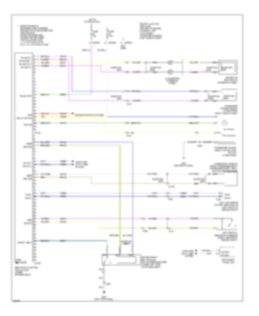
Supplemental Restraints Wiring Diagram for Ford E-350 Super Duty XL 2013
List of elements for Supplemental Restraints Wiring Diagram for Ford E-350 Super Duty XL 2013:
- (not used)
- (under right side of front passenger seat) passenger safety belt buckle pretensioner
- Ab cutoff sw
- Anti-lock brake system (abs) module (left front of engine compt)
- C144
- C155
- C210
- C2280b
- C2280d
- C263
- C310a
- C310b
- C3135
- Can2 +
- Can2 -
- Case grounded
- Cbp32
- Clockspring (steering wheel)
- Computer data lines system
- Cr101
- Cr103
- Cr116
- Cr120
- Cr122
- Cr167
- Cr201
- Cr225
- Dr ab fd 1
- Dr ab rtn 1
- Driver air bag module (steering wheel)
- Driver safety belt buckle switch/pretensioner (under left side of driver's seat)
- Engine controls system
- Ens
- Feed
- Feed return
- Fuse 10a
- Fuse 7.5a
- G201 (center of dash)
- G203 (left kick panel)
- Hot in start or run
- Hs can +
- Hs can -
- Hs can+
- Hs can-
- Instrument panel (ipc)
- Left frontal restraints sensor (front center of engine compt)
- Nca
- Pad ind
- Passenger air bag deactivation (pad) switch (if equipped)
- Passenger air bag module (if equipped) (right side of dash)
- Ps ab fd 1
- Ps ab ret 1
- Restraints control module (rcm) (under driver's seat)
- Return
- Rr101
- Rr103
- Rr120
- Rr122
- Rr129
- Run/start
- S239
- S264
- Safety belt
- Shorting bar
- Shorting bar is engaged when harness connector is disconnected from module (shorting bars are connected between the following pins: 1-2, 3-4 of conn c310a & 3-4, 13-14 of conn c310b)
- Smart junction box (sjb) (except stripped chassis: left kick panel) (stripped chassis: left side of dash)
- Vdb04
- Vdb05
- Vr213
- Vref sig rtn
 Русский