SUPPLEMENTAL RESTRAINTS
Supplemental Restraints Wiring Diagram for Ford Econoline E250 2003
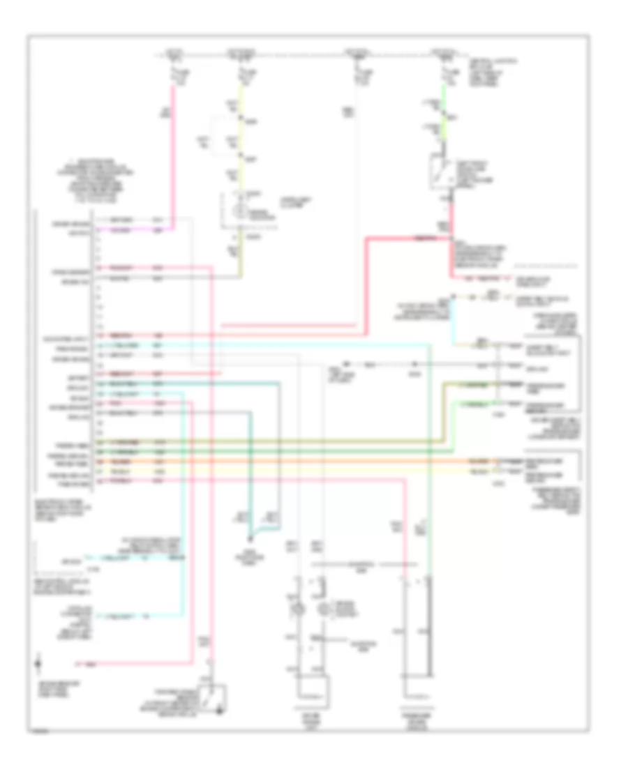
List of elements for Supplemental Restraints Wiring Diagram for Ford Econoline E250 2003:
- (in window regulator relay switch harn, near breakout to c237) s228
- Abs control module (at left side of engine compartment)
- Air bag bracket
- Air bag bracket (right side dash panel)
- Air bag ind
- Air bag indicator
- Air bag sliding contact
- Battery
- C135
- C220c
- C303
- C323
- Central junction box (cjb) (left side of dash, near kick panel)
- Crash sensor
- Data link connector (dlc) (partial) (below left side of dash)
- Door open input
- Driver air bag
- Driver air bag unit
- Driver door open input
- Driver safety belt retractor pretensioner (under driver seat)
- Electronic crash sensor (ecs) module (behind right side of dash)
- Feed
- Forward crash sensor (in front center of engine compartment, behind grille)
- Fuse 2.14 5a
- Fuse 2.19 10a
- Fuse 2.38 10a
- Fuse 2.4 15a
- G204 (left side of dash)
- G206 (right side dash)
- Ground
- Hot at all times
- Hot in run
- Hot in run or start
- Ignition
- Instrument cluster
- Iso bus
- Left front door ajar switch (left rocker panel)
- Nca
- Pass air bag
- Passenger air bag module
- Passenger safety belt retractor pretensioner (under passenger seat)
- Pnk
- Preten feed
- Preten return
- Pretensioner feed
- Pretensioner nca
- Pretensioner return
- Red/ pnk
- Red/pnk
- S201 (in main wiring harn, near breakout to electronic crash sensor module)
- S221
- S235
- S265
- S267
- S275 (in main wiring harn, near breakout to instrument cluster)
- Safety belt buckle sw input
- Safety belt buckle switch input
- Shorting bar
- Shorting bar engaged when module connector is disconnected from harness (shorting bars are connected between following pins: 1-15, 7-21 & 14-28)
- Warning buzzer/ chime module (behind center of dash)
 English