SUPPLEMENTAL RESTRAINTS
Supplemental Restraints Wiring Diagram for Ford Econoline E250 2005
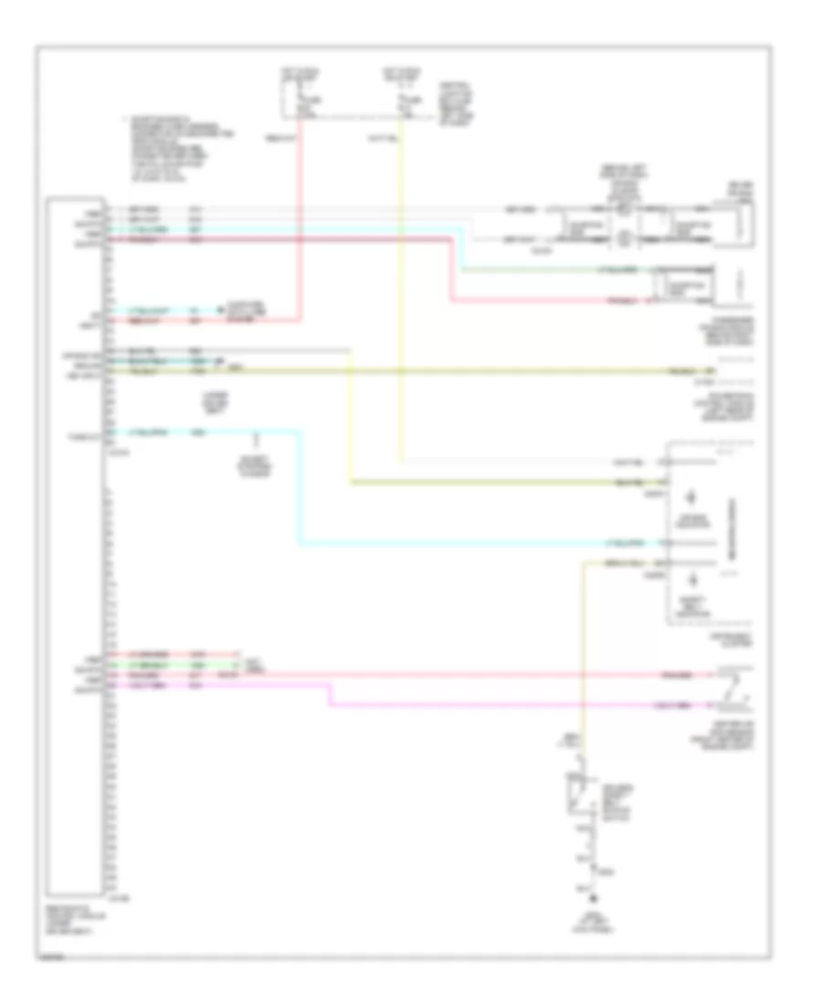
List of elements for Supplemental Restraints Wiring Diagram for Ford Econoline E250 2005:
- (behind left side of dash) air bag sliding contact
- (not used)
- (under
- Air bag ind ground vem input
- Air bag indicator
- C175a
- C218a
- C220a
- C220b
- C310a
- C310b
- C3135
- Center air bag sensor (front center of engine compt)
- Central junction box (cjb) (behind left side of dash)
- Computer data lines system
- Driver air bag unit
- Driver seat)
- Driver's safety belt buckle switch
- Except stripped chassis
- Fuse 10a
- Fuse 5a
- G201
- G204 (at left kick panel)
- Hot in run or start
- Instrument cluster
- Iso vbatt
- Microprocessor
- Nca
- Passenger air bag module (behind right side of dash)
- Powertrain control module (left rear of engine compt)
- Restraints control module (under driver seat)
- S235
- Safety belt indicator
- Shorting bar
- Shorting bar is engaged when harness connector is disconnected from module (shorting bars are connected between the following pins: 1-2, 3-4 & 15-16 of conn. c310a)
- Sig rtn
- Tone out
- Vref
 English