SUPPLEMENTAL RESTRAINTS
Supplemental Restraints Wiring Diagram for Ford Econoline E250 2008
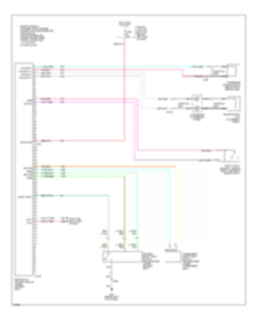
List of elements for Supplemental Restraints Wiring Diagram for Ford Econoline E250 2008:
- C218a
- C256
- C310a
- C310b
- Can +
- Can -
- Central junction box (cjb) (behind left side of dash)
- Clockspring (in steering wheel)
- Computer data lines system
- Dr ab fd 1
- Dr ab rtn 1
- Driver air bag unit (in steering wheel)
- Driver's safety belt buckle pretensioner (under driver's seat)
- Feed
- Front impact severity sensor (front center of engine compt)
- Fuse 10a
- G204 (behind left kick panel)
- Hot in run or start
- Nca
- Passenger air bag module (behind right side of dash)
- Passenger's safety belt buckle pretensioner (under passenger's seat)
- Ps ab fd 1
- Ps ab rtn 1
- Restraints control module (under driver's seat)
- Return
- Run/start
- S250
- Safety belt
- Shorting bar
- Shorting bar is engaged when harness connector is disconnected from module (shorting bars are connected between the following pins: 1-2, 3-4 & 15-16 of conn c310a)
- Vref sig rtn
 English