SUPPLEMENTAL RESTRAINTS
Supplemental Restraints Wiring Diagram (1 of 2) for Ford Expedition 2006

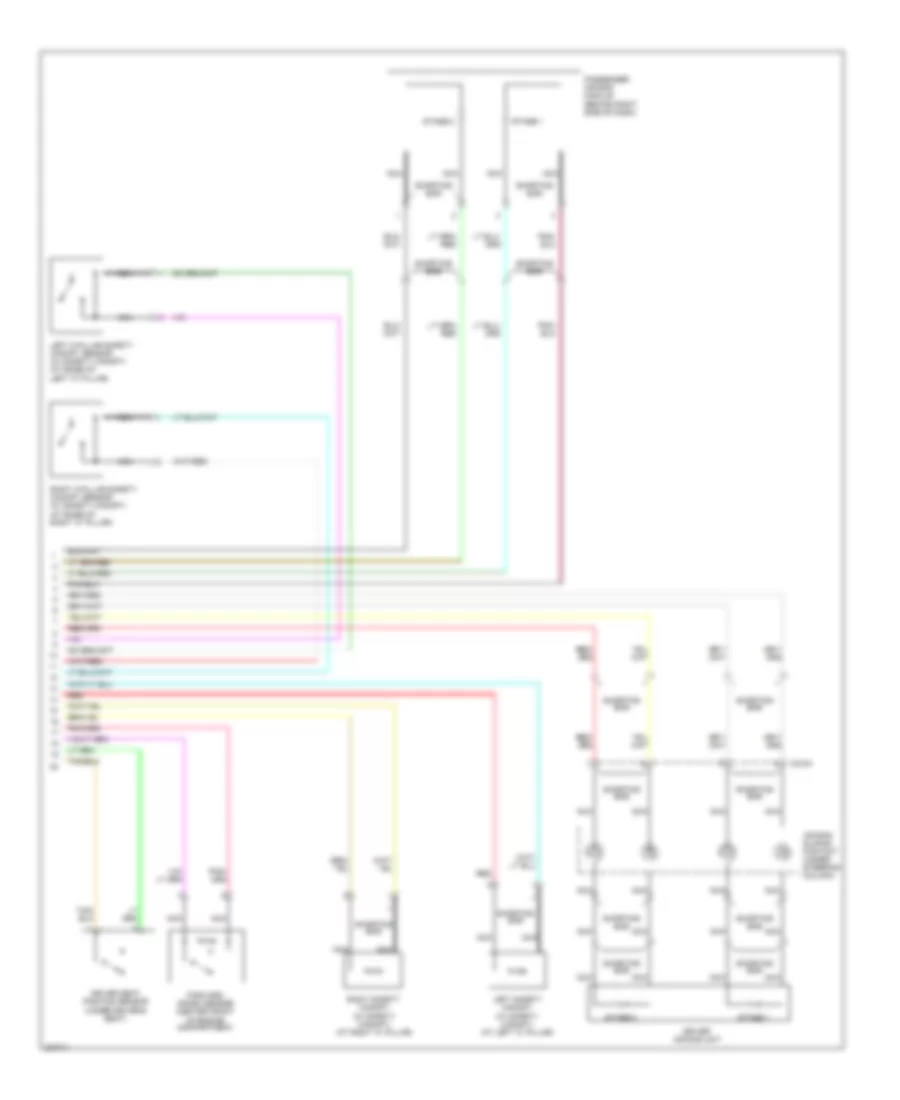
List of elements for Supplemental Restraints Wiring Diagram (1 of 2) for Ford Expedition 2006:
- (behind left kick panel) g301
- A/blp
- Air bag ind ctrl
- Air bag stage 1+
- Air bag stage 1-
- Air bag stage 2+
- Air bag stage 2-
- C175b
- C220a
- C220b
- C270f
- C270j
- C310a
- C310b
- Central junction box (cjb) (behind right kick panel)
- Computer data lines system
- Connector (dlc) (under left side of dash)
- Data link
- Driver safety belt buckle switch (in driver safety belt buckle assembly)
- Driver safety belt pretensioner (in driver safety belt buckle assembly)
- Fuse 10a
- Fuse 5a
- Hot in run or start
- Instrument cluster
- Iso
- Left door safety canopy sensor (in bottom of left front door)
- Logic ground
- Nca
- Passenger safety belt buckle switch (in passenger safety belt buckle assembly)
- Passenger safety belt pretensioner (in passenger safety belt buckle assembly)
- Pin shorting bars engaged when module connector is disconnected from harness (shorting bars are connected between pins: 1-2, 3-4, 5-6 & 13-14 c310a 3-4 & 5-6 c310b)
- Power train control module (pcm) (on right side of firewall)
- Rdi
- Red
- Ref/gnd
- Restraint control module (below center console)
- Right door safety canopy sensor (in bottom of right door)
- S282 (in main harness, near breakout to center of dash)
- S300 (expedition) (in body main harness, near breakout to center console)
- S308
- S308 (in body main harness, near breakout to restraints control module)
- S320 (in body main harness, near breakout to center console)
- Shorting bar
- Signal
- Signal +
- Signal -
- Tone driver
- Tone req
- Vpwr
- W/ safety canopy
Supplemental Restraints Wiring Diagram (2 of 2) for Ford Expedition 2006
List of elements for Supplemental Restraints Wiring Diagram (2 of 2) for Ford Expedition 2006:
- Air bag sliding contact (under steering column)
- C218a
- Driver air bag unit
- Driver seat position sensor (under driver's seat)
- Forward crash sensor (center front of engine compartment)
- Left c-pillar safety canopy sensor (w/ safety canopy) (at base of left "c" pillar)
- Left safety canopy (w/ safety canopy) (at left "c" pillar)
- Nca
- Passenger air bag module (behind right side of dash)
- Red
- Right c-pillar safety canopy sensor (w/ safety canopy) (at base of right "c" pillar)
- Right safety canopy (w/ safety canopy) (at right "c" pillar)
- Shorting bar
- Stage 1
- Stage 2