SUPPLEMENTAL RESTRAINTS
Supplemental Restraints Wiring Diagram (1 of 2) for Ford Explorer 2004

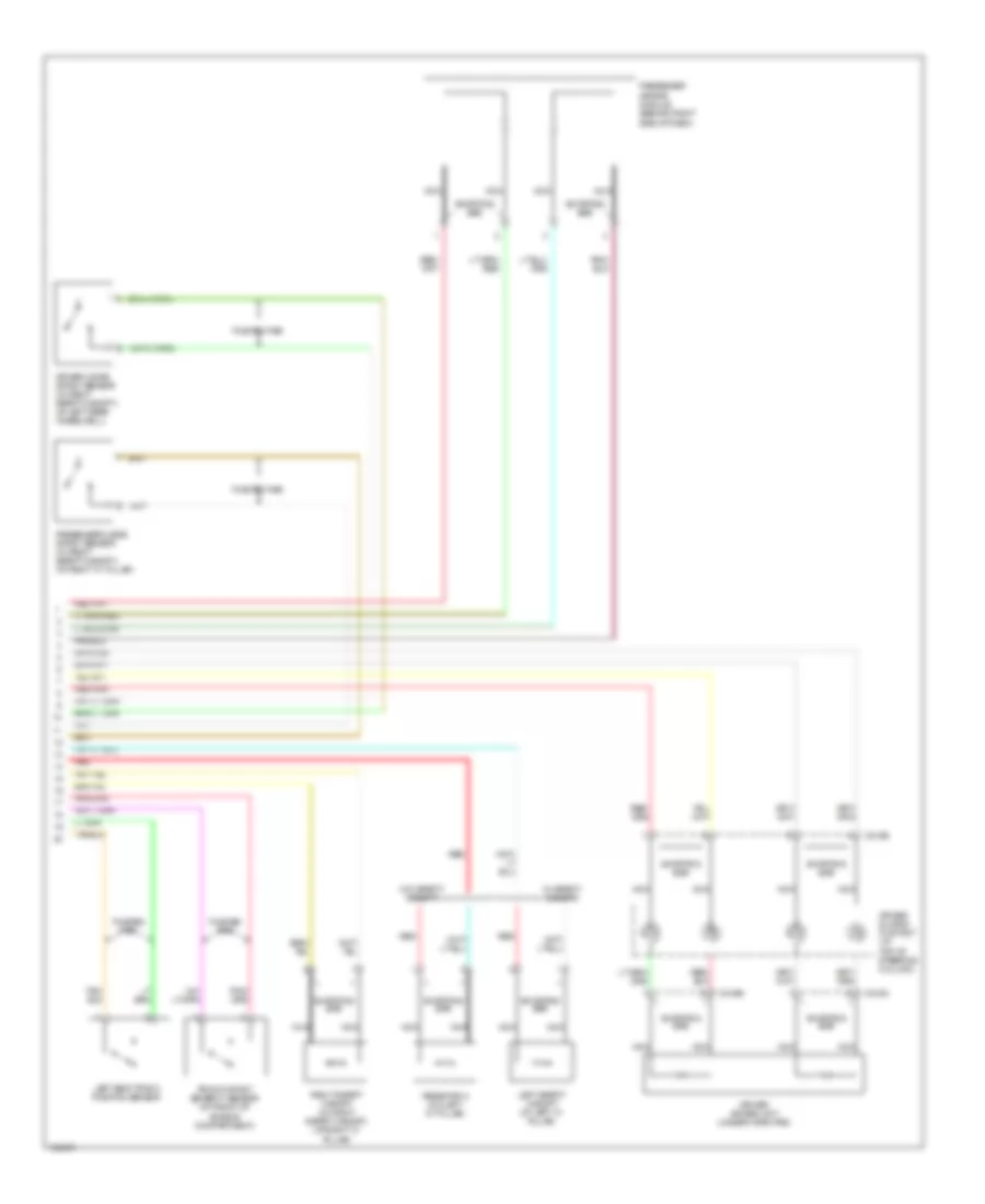
List of elements for Supplemental Restraints Wiring Diagram (1 of 2) for Ford Explorer 2004:
- (in main harn, near breakout to audio unit)
- (under center console) g205
- Air bag ind
- Air bag ind ctrl
- Battery
- Battery junction box (bjb) (left side of engine compartment, at fender apron)
- C1117
- C175b
- C220a
- C220b
- C228b
- C270e
- C310a
- C310b
- Central junction box (cjb) (behind left side of dash)
- Computer data lines system
- Data link connector (dlc) (behind left side of dash)
- Driver 1 side impact sensor (at base of left "b" pillar)
- Driver safety belt buckle pretensioner (under driver seat)
- Driver safety belt buckle switch (under driver seat)
- Electronic automatic temperature control (eatc) module (behind center of dash)
- Fuse 10a
- Fuse 15a
- G301 (under center console)
- Hot at all times
- Hot in run or start
- Instrument cluster
- Iso
- J/c 1
- Logic ground
- Micro- processor
- Nca
- Note: 1: unbuckled 2: buckled
- Passenger 1 side impact sensor (at base of right "b"pillar)
- Passenger safety belt buckle pretensioner (under passenger seat)
- Passenger safety belt buckle switch (under passenger seat)
- Pin shorting bars engaged when module connector is disconnected from harness (shorting bars are connected between pins: 1-2, 3-4, 5-6 & 13-14 c310a 3-4 & 5-6 c310b
- Powertrain control module (at right side engine bulkhead)
- Red
- Ref/gnd
- Restraints control module (below center console)
- S228
- S232 (in main harness, near breakout to central junction box)
- S333 (near breakout to restraints control module)
- See note
- Shorting bar
- Signal
- Signal +
- Signal -
- Tone
- Tone req
- Twisted pair
- Vbatt
- Vpwr
- W/ dual zone eatc
- W/ right safety canopy
Supplemental Restraints Wiring Diagram (2 of 2) for Ford Explorer 2004
List of elements for Supplemental Restraints Wiring Diagram (2 of 2) for Ford Explorer 2004:
- Air bag sliding contact (at top of steering column)
- C216a
- C216b
- C218b
- Driver 2 side impact sensor (w/ right safety canopy) (at left rear wheelwell)
- Driver air bag unit (under horn pad)
- Front impact severity sensor (at front of engine compartment)
- Left safety canopy (at left "c" pillar)
- Left seat track position sensor
- Nca
- Passenger 2 side impact sensor (w/ right safety canopy) (at right "c" pillar)
- Passenger air bag module (behind right side of dash)
- Red
- Resistor a (on left "c" pillar)
- Right safety canopy (w/ right safety canopy) (at right "c" pillar)
- Shorting bar
- Twisted pair
- W/ safety canopy
- W/o safety canopy