SUPPLEMENTAL RESTRAINTS
Supplemental Restraint Wiring Diagram for Ford Pickup F350 Super Duty 1999
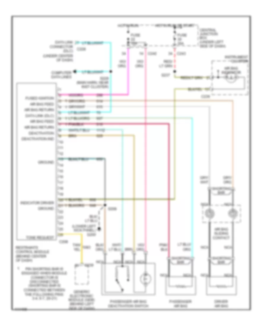
List of elements for Supplemental Restraint Wiring Diagram for Ford Pickup F350 Super Duty 1999:
- (lower left kick panel) g200
- (under center of dash)
- Air bag feed
- Air bag indicator
- Air bag return
- Air bag sliding contact
- C208
- C236
- C239
- C242
- C243
- Central junction box (under left side of dash)
- Computer data lines
- Connector c228 (dlc)
- Data link
- Data link (dlc)
- Deactivation
- Deactivation ind
- Driver air bag
- Fuse 10a
- Fuse 30a
- Fused ignition
- Generic electronic module (gem) (behind left side of dash)
- Ground
- Hot in run
- Hot in run or start
- Indicator driver
- Instrument cluster
- Nca
- Passenger air bag
- Passenger air bag deactivation switch
- Pin shorting bar is engaged when module connector is disconnected (shorting bar is connected between the following pins: 3-4, 6-7, 20-21)
- Restraints control module (behind center of dash)
- S208
- S229 (main harn, near inst cluster)
- S237
- Shorting bar
- Tone request
 English