SUPPLEMENTAL RESTRAINTS
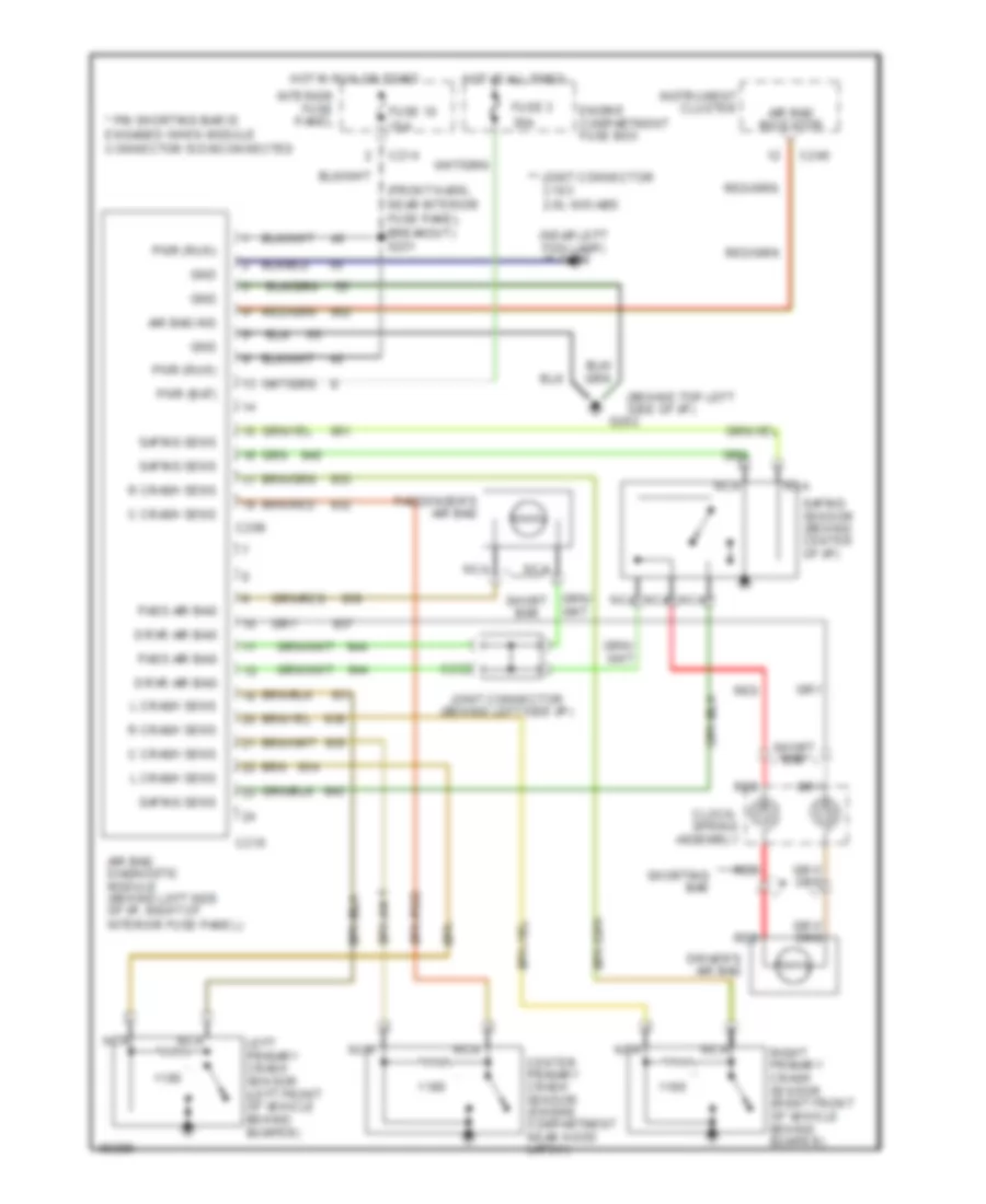
Supplemental Restraint Wiring Diagram for Ford Probe GT 1997
List of elements for Supplemental Restraint Wiring Diagram for Ford Probe GT 1997:
- (behind top left side of i/p)
- (front harn, near interior fuse panel breakout) s231
- (near left fog lamp) g106
- * pin shorting bar is engaged when module connector is disconnected
- ** joint connector
- Air bag diagnostic module (behind left side of i/p, right of interior fuse panel)
- Air bag ind
- Air bag indicator
- C crash sens
- C103 2.0l w/o abs
- C209
- C210
- C214
- C240
- C262
- Center primary crash sensor (engine compartment near hood latch)
- Clock- spring assembly
- Driver's air bag
- Drvr air bag
- Engine compartment fuse box
- Fuse 10 15a
- Fuse 3 30a
- G202
- Gnd
- Hot at all times
- Hot in run or start
- Instrument cluster
- Interior fuse panel
- Joint connector (behind left side i/p)
- L crash sens
- Left primary crash sensor (left front of vehicle behind bumper)
- Nca
- Pass air bag
- Passenger's air bag
- Pwr (bat)
- Pwr (run)
- R crash sens
- Red
- Right primary crash sensor (right front of vehicle behind bumper)
- Safing sens
- Safing sensor (behind center of i/p)
- Short bar
- Shorting bar
 English