SUPPLEMENTAL RESTRAINTS
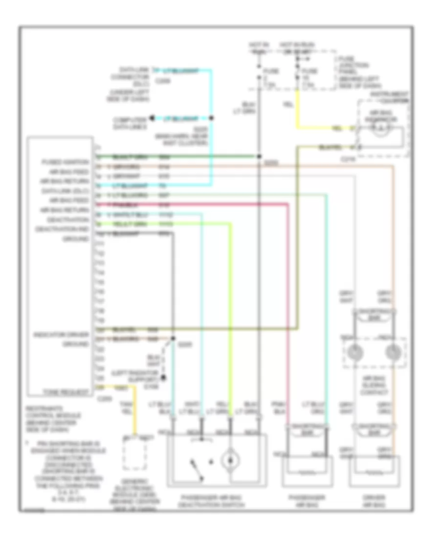
Supplemental Restraint Wiring Diagram for Ford Ranger 1999
List of elements for Supplemental Restraint Wiring Diagram for Ford Ranger 1999:
- (left radiator support) g108
- (under left side of dash)
- Air bag feed
- Air bag indicator
- Air bag return
- Air bag sliding contact
- C216
- C221
- C250
- Computer data lines
- Connector c209 (dlc)
- Data link
- Data link (dlc)
- Deactivation
- Deactivation ind
- Driver air bag
- Fuse 7.5a
- Fuse junction panel (behind left side of dash)
- Fused ignition
- Generic electronic module (gem) (behind center side of dash)
- Ground
- Hot in run
- Hot in run or start
- Indicator driver
- Instrument cluster
- Nca
- Passenger air bag
- Passenger air bag deactivation switch
- Pin shorting bar is engaged when module connector is disconnected (shorting bar is connected between the following pins: 3-4, 6-7, 8-10, 20-21)
- Restraints control module (behind center side of dash)
- S205
- S225 (main harn, near inst cluster)
- S250
- S64
- Shorting bar
- Tone request
 English