SUPPLEMENTAL RESTRAINTS
Supplemental Restraint Wiring Diagram for Ford Ranger 2000
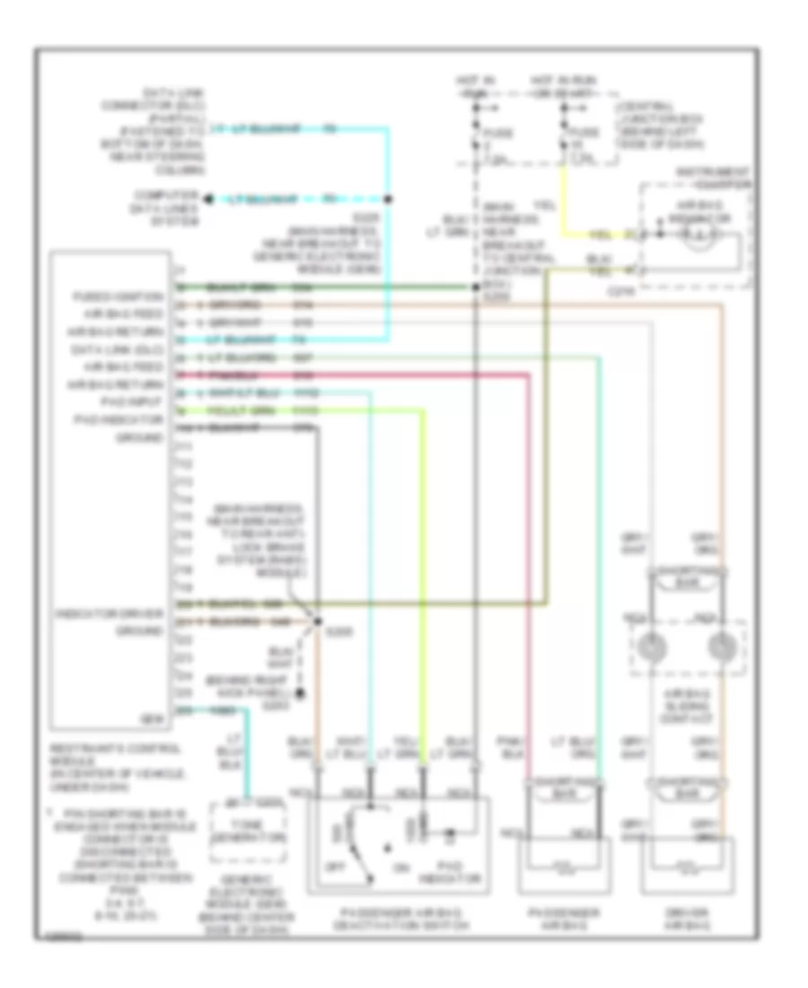
List of elements for Supplemental Restraint Wiring Diagram for Ford Ranger 2000:
- (behind right kick panel) g203
- (main harness, near breakout to central junction box) s250
- (main harness, near breakout to rear anti- lock brake system (rabs) module)
- Air bag feed
- Air bag indicator
- Air bag return
- Air bag sliding contact
- C216
- C221
- Central junction box (behind left side of dash)
- Computer data lines system
- Data link (dlc)
- Data link connector (dlc) (partial) (fastened to bottom of dash, near steering column)
- Driver air bag
- Fuse 7.5a
- Fused ignition
- Gem
- Generic electronic module (gem) (behind center side of dash)
- Ground
- Hot in run
- Hot in run or start
- Indicator driver
- Instrument cluster
- Nca
- Off
- Ohms
- Pad indicator
- Pad input
- Passenger air bag
- Passenger air bag deactivation switch
- Pin shorting bar is engaged when module connector is disconnected (shorting bar is connected between pins: 3-4, 6-7, 8-10, 20-21)
- Restraints control module (in center of vehicle, under dash)
- S205
- S225 (main harness, near breakout to generic electronic module (gem))
- Shorting bar
- Tone generator
 English