SUPPLEMENTAL RESTRAINTS
Supplemental Restraint Wiring Diagram for Ford Taurus LX 1999
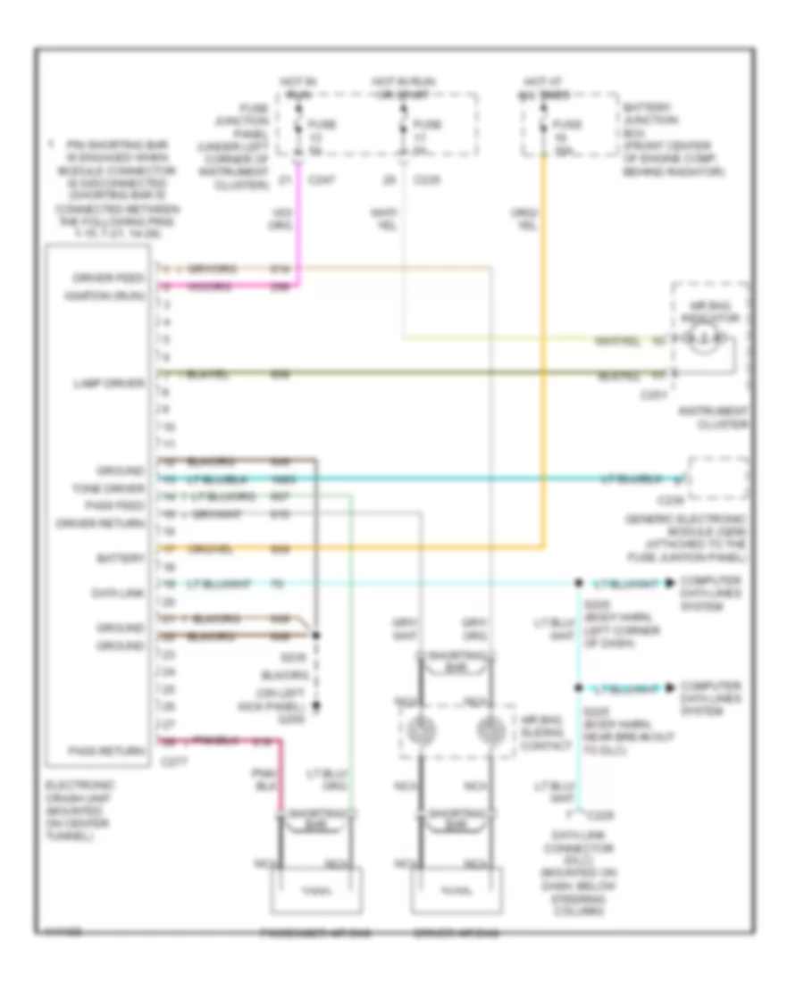
List of elements for Supplemental Restraint Wiring Diagram for Ford Taurus LX 1999:
- (on left kick panel) g200
- Air bag indicator
- Air bag sliding contact
- Battery
- Battery junction box (front center of engine comp, behind radiator)
- C229
- C235
- C236
- C247
- C251
- C277
- Computer data lines system
- Data link
- Data link connector (dlc) (mounted on dash, below steering column)
- Driver air bag
- Driver feed
- Driver return
- Electronic crash unit (mounted on center tunnel)
- Fuse 10a
- Fuse 5a
- Fuse junction panel (under left corner of instrument cluster)
- Generic electronic module (gem) (attached to the fuse juntion panel)
- Ground
- Hot at all times
- Hot in run
- Hot in run or start
- Ignition (run)
- Instrument cluster
- Lamp driver
- Nca
- Pass feed
- Pass return
- Passenger air bag
- Pin shorting bar is engaged when module connector is disconnected (shorting bar is connected between the following pins: 1-15, 7-21, 14-28)
- S225 (body harn, near breakout to dlc)
- S235
- Shorting bar
- Tone driver
 English