SUPPLEMENTAL RESTRAINTS
Supplemental Restraint Wiring Diagram for Ford Windstar 1999
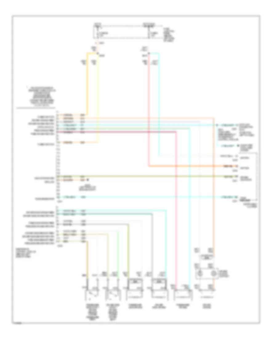
List of elements for Supplemental Restraint Wiring Diagram for Ford Windstar 1999:
- (at bottom left of dash)
- Air bag indicator c241
- Air bag sliding contact
- C201
- C231
- C232
- C240
- C251
- Computer data lines system
- Connector (dlc)
- Data link
- Data link (dlc)
- Driver air bag
- Driver air bag feed
- Driver air bag return
- Driver side air bag
- Driver side air bag feed
- Driver side air bag return
- Driver side impact air bag sensor (under driver seat)
- Driver side sensor feed
- Driver side sensor return
- Fuse 26 10a
- Fuse 9 10a
- Fuse junction panel (behind left side of dash)
- Fused ignition
- G102 (left front of engine compt)
- Ground
- Hot in run
- Hot in run or start
- Ignition
- Indicator driver
- Instrument cluster
- Nca
- Pass air bag feed
- Pass air bag return
- Pass side air bag feed
- Pass side air bag return
- Pass side sensor feed
- Pass side sensor return
- Passenger side air bag
- Passenger air bag
- Passenger side impact air bag sensor (under passenger seat)
- Pin shorting bar is engaged when module connector is disconnected (shorting bar is connected between the following pins: 3-4, 6-7, 20-21)
- Restraints control module (behind left side of dash)
- S209
- S210 (main harn, near breakout to restraint control module)
- S216
- Shorting bar
- Tone generator
- Tone request c231
 English