SUPPLEMENTAL RESTRAINTS
Supplemental Restraint Wiring Diagram for Ford Windstar LX 1997
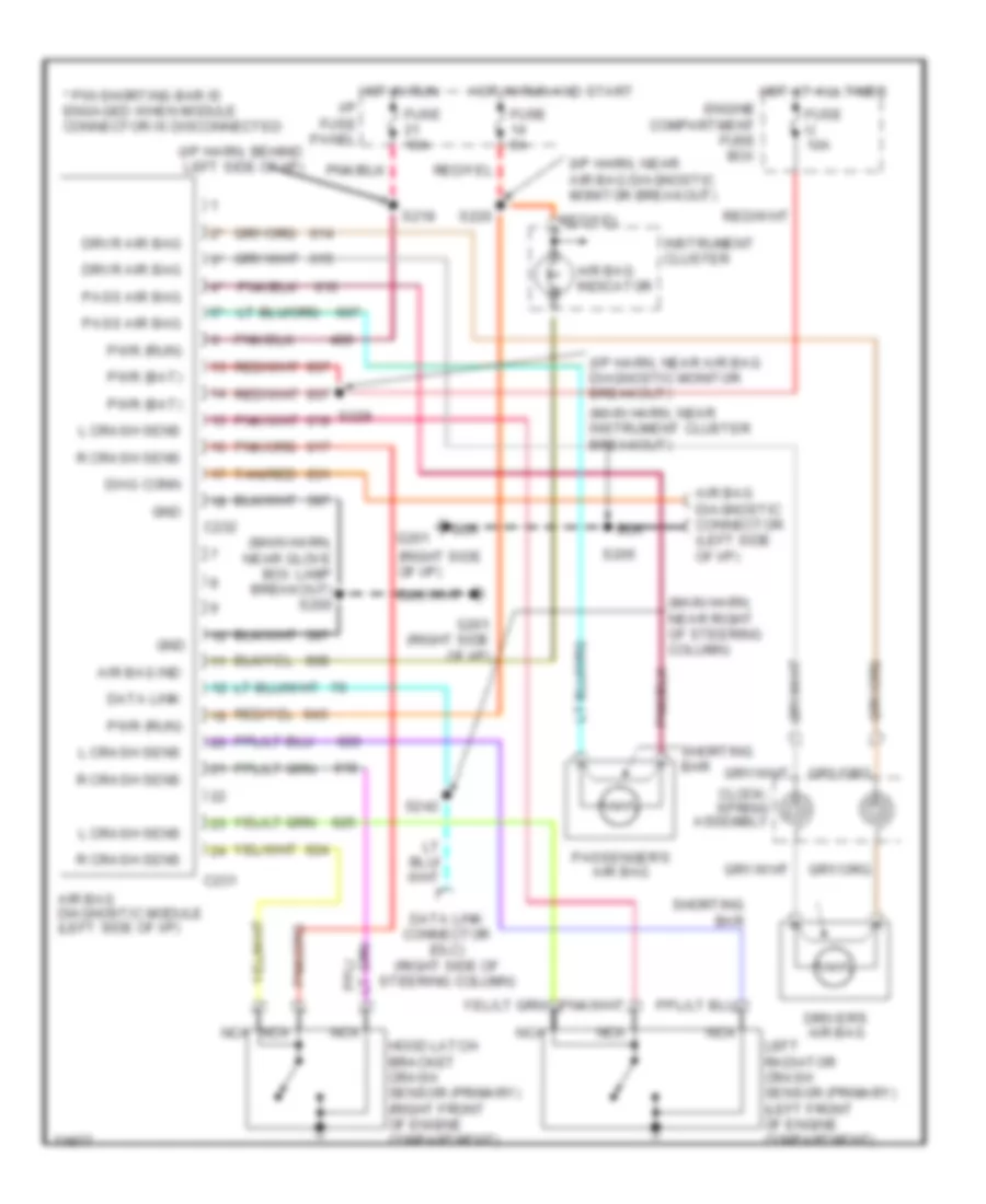
List of elements for Supplemental Restraint Wiring Diagram for Ford Windstar LX 1997:
- (i/p harn, behind left side of i/p)
- (i/p harn, near air bag diagnostic monitor breakout)
- (main harn, near glove box lamp breakout) s200
- (main harn, near instrument cluster breakout)
- (main harn, near right of steering column)
- (right side of i/p)
- * pin shorting bar is engaged when module connector is disconnected
- Air bag diagnostic connector (left side of i/p)
- Air bag diagnostic module (left side of i/p)
- Air bag ind
- Air bag indicator
- C231
- C232
- Clock- spring assembly
- Data link
- Data link connector (dlc) (right side of steering column)
- Diag conn
- Driver's air bag
- Drvr air bag
- Engine compartment fuse box
- Fuse 10a
- Fuse 5a
- Fuse u 10a
- G201
- G201 (right side of i/p)
- Gnd
- Hood latch bracket crash sensor (primary) (right front of engine compartment)
- Hot at all times
- Hot in run and start
- Hot in run i/p fuse panel
- Instrument cluster
- L crash sens
- Left radiator crash sensor (primary) (left front of engine compartment)
- Nca
- Pass air bag
- Passenger's air bag
- Pwr (bat)
- Pwr (run)
- R crash sens
- S205
- S218
- S220
- S229
- S242
- Shorting bar
- Tan/red
 English