SUPPLEMENTAL RESTRAINTS
Supplemental Restraint Wiring Diagram for GMC Cab & Chassis C3500 1996
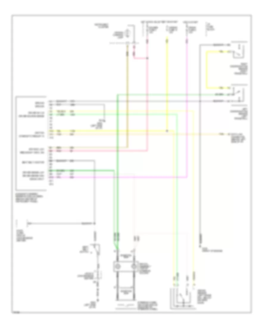
List of elements for Supplemental Restraint Wiring Diagram for GMC Cab & Chassis C3500 1996:
- A10
- A11
- A12
- Air bag fuse 10 10a
- Air bag warning lamp
- Arming sensor (left frame rail, below driver's door)
- Audio alarm module (convenience center)
- B10
- B11
- B12
- Crank fuse 8 10a
- Crank input
- Data link connector (behind left side of i/p)
- Diagnostic energy reserve module (derm) (behind center of instrument panel)
- Diagnostic requst in
- Driver 36 vlr
- Driver sense high
- Driver sense low
- Driver source sense
- G125 (front of engine)
- G202 (left side of i/p)
- Gauges fuse 4 10a
- Ground
- Hot in run, bulb test or start
- Hot in start
- I/p fuse block
- Ignition
- Instrument cluster
- J/b c210 (convenience center)
- Left discriminating sensor (left frame rail)
- Nca
- Pnk
- Redundant indic, ign
- Right discriminating sensor (right frame rail)
- Seat belt monitor
- Seat belt switch
- Shorting bar
- Sir coil assembly (top of steering column)
- Sir indic low
- Steering wheel inflator module (mounted on steering wheel)
- Tan
 English