SUPPLEMENTAL RESTRAINTS
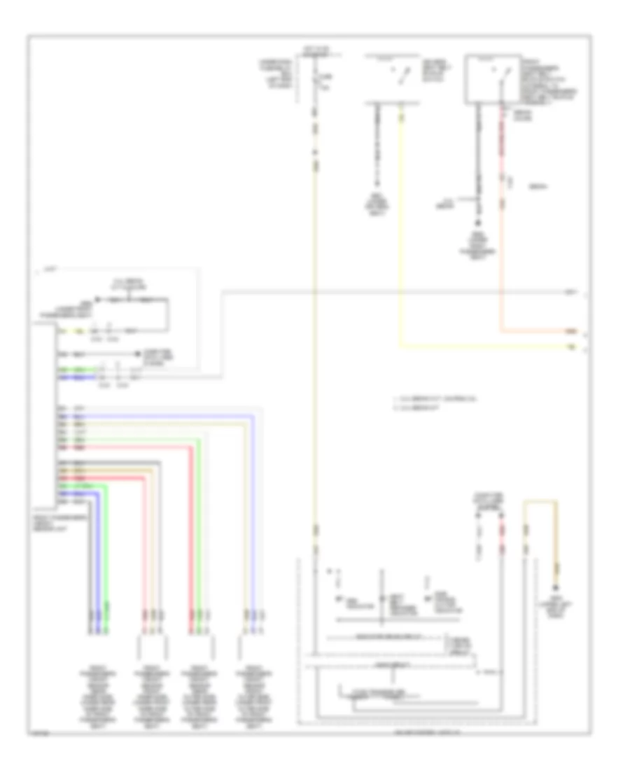
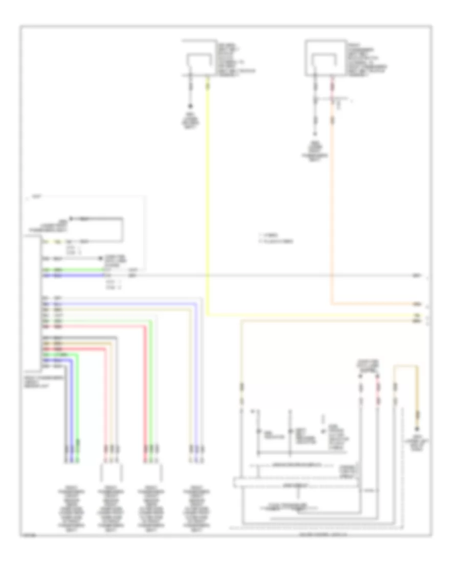
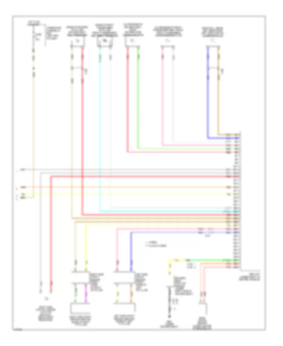
Supplemental Restraints Wiring Diagram, Except Hybrid (1 of 3) for Honda Accord Plug-In 2014

List of elements for Supplemental Restraints Wiring Diagram, Except Hybrid (1 of 3) for Honda Accord Plug-In 2014:
- (under center console) g504
- A10
- A11
- A12
- A13
- A14
- A15
- A16
- A17
- A18
- A19
- A20
- A21
- A22
- A23
- A24
- A25
- A26
- A27
- A28
- A29
- A30
- A31
- A32
- A33
- A34
- A35
- A36
- A37
- A38
- A39
- C101
- C109
- Cable reel (in steering column)
- Center junction box
- Computer data lines system
- Driver's air bag inflator (in steering wheel)
- Front passenger's air bag cut-off indicator
- Front passenger's air bag inflator (behind glove box)
- Fuse 10a
- Fuse 7.5a
- Hot in on or start
- Interior lights system
- Left front impact sensor (behind left side of front bumper)
- R13
- Red
- Right front impact sensor (behind right side of front bumper)
- Srs unit (under front of center console)
- Under-dash fuse/relay box (left end of dash)
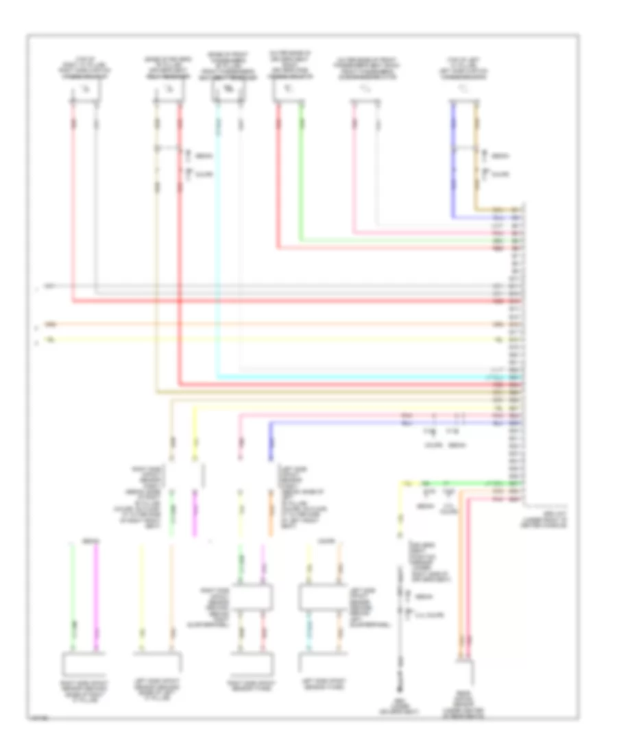
Supplemental Restraints Wiring Diagram, Except Hybrid (2 of 3) for Honda Accord Plug-In 2014
List of elements for Supplemental Restraints Wiring Diagram, Except Hybrid (2 of 3) for Honda Accord Plug-In 2014:
- 2.4l sedan
- 2.4l sedan cvt & coupe
- 2.4l sedan cvt, coupe & 3.5l
- 2.4l sedan m/t
- A17
- A19
- A20
- A32
- C121
- Computer data lines system
- Coupe
- Driver's seat belt buckle switch
- F-can h
- F-can l
- F-can transceiver
- Forced turn on circuit
- Front passenger's seat belt buckle switch (integral to front passenger's seat belt buckle assembly)
- Front passenger's weight sensor (front inner side) (under front inner side of front passenger's seat)
- Front passenger's weight sensor (front outer side) (under front outer side of front passenger's seat)
- Front passenger's weight sensor (rear inner side) (under rear inner side of front passenger's seat)
- Front passenger's weight sensor (rear outer side) (under rear outer side of front passenger's seat)
- Front passenger's weight sensor unit
- Fuse 7.5a
- G502 (upper left end of dash)
- G651 (under driver's seat)
- G652 (under front passenger's seat)
- Gauge control module
- Hot in on or start
- Indicator drive circuit
- M11
- Main circuit
- Red
- Seat belt reminder indicator
- Sedan
- Side air bag cut-off indicator
- Srs indicator
- Under-dash fuse/relay box (left end of dash)
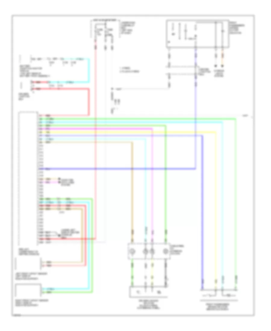
Supplemental Restraints Wiring Diagram, Except Hybrid (3 of 3) for Honda Accord Plug-In 2014
List of elements for Supplemental Restraints Wiring Diagram, Except Hybrid (3 of 3) for Honda Accord Plug-In 2014:
- (base of driver's "b" pillar) driver's seat belt tensioner
- (base of front passenger's "b" pillar) front passenger's seat belt tensioner
- (outer edge of driver's seat back) driver's side air bag inflator
- (outer edge of front passenger's seat back) front passenger's side air bag inflator
- (top of left "c" pillar) left side curtain air bag inflator
- (top of right "c" pillar) right side curtain air bag inflator
- 2.4l coupe
- B10
- B11
- B12
- B13
- B14
- B15
- B16
- B17
- B18
- B19
- B20
- B21
- B22
- B23
- B24
- B25
- B26
- B27
- B28
- B29
- B30
- B31
- B32
- B33
- B34
- B35
- B36
- B37
- B38
- B39
- C118
- C119
- C122
- C124
- C125
- Coupe
- Driver's seat position sensor (under right side of driver's seat)
- G651 (under driver's seat)
- Left side impact sensor (first) (sedan: base of left "b" pillar) (coupe: on floor, at outer side of left front seat)
- Left side impact sensor (second) (base of left "c" pillar)
- Left side impact sensor (second) (behind left quarterpanel)
- Left side impact sensor (third)
- Pnk
- Rear safing sensor (under center of rear seats)
- Red
- Right side impact sensor (first) (sedan: base of right "b" pillar) (coupe: on floor, at outer side of right front seat)
- Right side impact sensor (second) (base of right "c" pillar)
- Right side impact sensor (second) (behind right quarterpanel)
- Right side impact sensor (third)
- Sedan
- Srs unit (under front of center console)
Supplemental Restraints Wiring Diagram, Hybrid (1 of 3) for Honda Accord Plug-In 2014
List of elements for Supplemental Restraints Wiring Diagram, Hybrid (1 of 3) for Honda Accord Plug-In 2014:
- (under left side of center console) g504
- A10
- A11
- A12
- A13
- A14
- A15
- A16
- A17
- A18
- A19
- A20
- A21
- A22
- A23
- A24
- A25
- A26
- A27
- A28
- A29
- A30
- A31
- A32
- A33
- A34
- A35
- A36
- A37
- A38
- A39
- Battery condition monitor module (top left rear of battery pack assembly)
- C101
- C104
- C108
- C109
- C118
- C126
- C129
- C404
- Cable reel (in steering column)
- Center junction box
- Computer data lines system
- Driver's air bag inflator (plug-in hybrid: in steering wheel)
- Driver's junction box
- Front passenger's air bag cut-off indicator
- Front passenger's air bag inflator (behind glove box)
- Fuse 10a
- Fuse 7.5a
- Hot in on or start
- Hybrid
- Interior lights system
- Left front impact sensor (left side of radiator support)
- Plug-in hybrid
- R13
- Red
- Right front impact sensor (right side of radiator support)
- Srs unit (under front of center console)
- Under-dash fuse/relay box (left end of dash)
Supplemental Restraints Wiring Diagram, Hybrid (2 of 3) for Honda Accord Plug-In 2014
List of elements for Supplemental Restraints Wiring Diagram, Hybrid (2 of 3) for Honda Accord Plug-In 2014:
- A17
- A19
- A20
- A32
- C123
- C131
- Computer data lines system
- Driver's seat belt buckle switch (integral to driver's seat belt buckle assembly)
- F-can h
- F-can l
- F-can transceiver
- Forced turn on circuit
- Front passenger's seat belt buckle switch (integral to front passenger's seat belt buckle assembly)
- Front passenger's weight sensor (front inner side) (under front inner side of front passenger's seat)
- Front passenger's weight sensor (front outer side) (under front outer side of front passenger's seat)
- Front passenger's weight sensor (rear inner side) (under rear inner side of front passenger's seat)
- Front passenger's weight sensor (rear outer side) (under rear outer side of front passenger's seat)
- Front passenger's weight sensor unit
- G502 (upper left end of dash)
- G651 (under driver's seat)
- G652 (under front passenger's seat)
- Gauge control module
- Hybrid
- Indicator drive circuit
- Main circuit
- Plug-in hybrid
- Red
- Seat belt reminder indicator
- Side air bag cut-off indicator (plug-in hybrid)
- Srs indicator
Supplemental Restraints Wiring Diagram, Hybrid (3 of 3) for Honda Accord Plug-In 2014
List of elements for Supplemental Restraints Wiring Diagram, Hybrid (3 of 3) for Honda Accord Plug-In 2014:
- (base of driver's "b" pillar) driver's seat belt tensioner
- (base of front passenger's "b" pillar) front passenger's seat belt tensioner
- (outer edge of driver's seat back) driver's side air bag inflator
- (outer edge of front passenger's seat back) front passenger's side air bag inflator
- (roof rail, above left rear door) left side curtain air bag inflator
- B10
- B11
- B12
- B13
- B14
- B15
- B16
- B17
- B18
- B19
- B20
- B21
- B22
- B23
- B24
- B25
- B26
- B27
- B28
- B29
- B30
- B31
- B32
- B33
- B34
- B35
- B36
- B37
- B38
- B39
- C120
- C121
- C125
- C132
- Driver's seat position sensor (under right side of driver's seat)
- Fuse 10a
- G651 (under driver's seat)
- Hot in on or start
- Hybrid
- Left side impact sensor (first) (base of left "b" pillar)
- Left side impact sensor (second) (base of left "c" pillar)
- M11
- Plug-in hybrid
- Pnk
- Rear safing sensor (under center of rear seats)
- Red
- Right side curtain air bag inflator (roof rail, above right rear door)
- Right side impact sensor (first) (base of right "b" pillar)
- Right side impact sensor (second) (base of right "c" pillar)
- Srs unit (under front of center console)
- Under-dash fuse/relay box (left end of dash)