
SUPPLEMENTAL RESTRAINTS
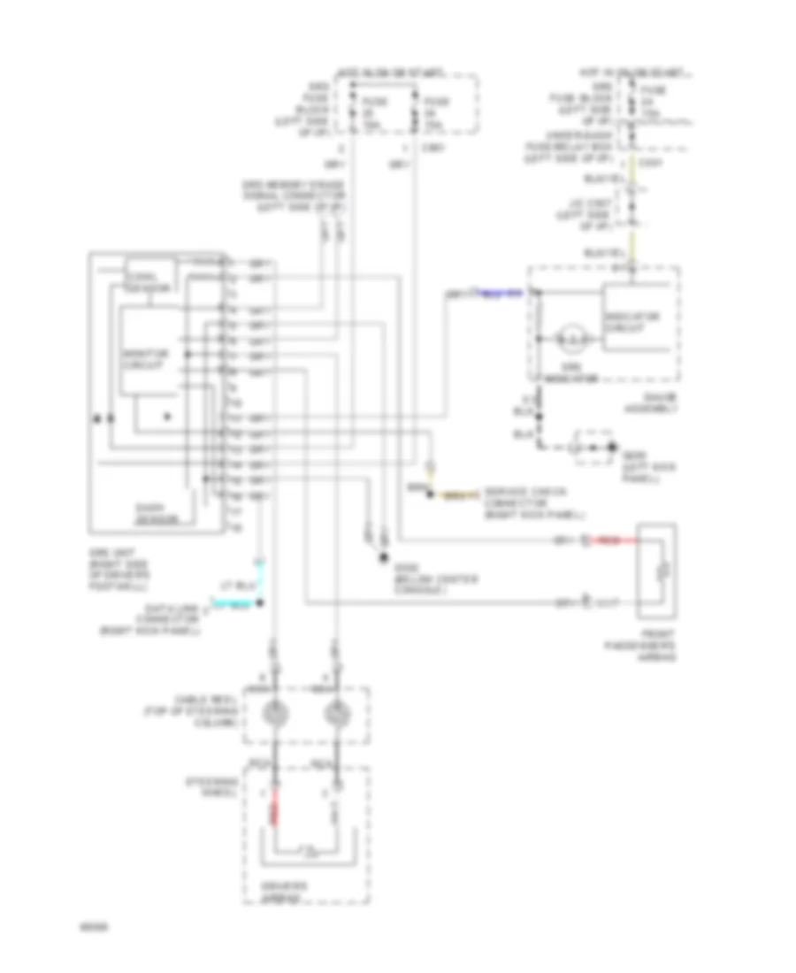
Supplemental Restraint Wiring Diagram for Honda Civic Si 1994
List of elements for Supplemental Restraint Wiring Diagram for Honda Civic Si 1994:
AIR CONDITIONINGANTI-LOCK BRAKESCOOLING FANDEFOGGERSANTI-THEFTCOMPUTER DATA LINESHORNCRUISE CONTROLEXTERIOR LIGHTSHEADLIGHTSENGINE PERFORMANCEGROUND DISTRIBUTIONINSTRUMENT CLUSTERPOWER DISTRIBUTIONPOWER DOOR LOCKSINTERIOR LIGHTSPOWER MIRRORSPOWER TOP/SUNROOFPOWER WINDOWSSHIFT INTERLOCKSSUPPLEMENTAL RESTRAINTSSTARTING/CHARGINGRADIOWARNING SYSTEMSWIPER/WASHER