
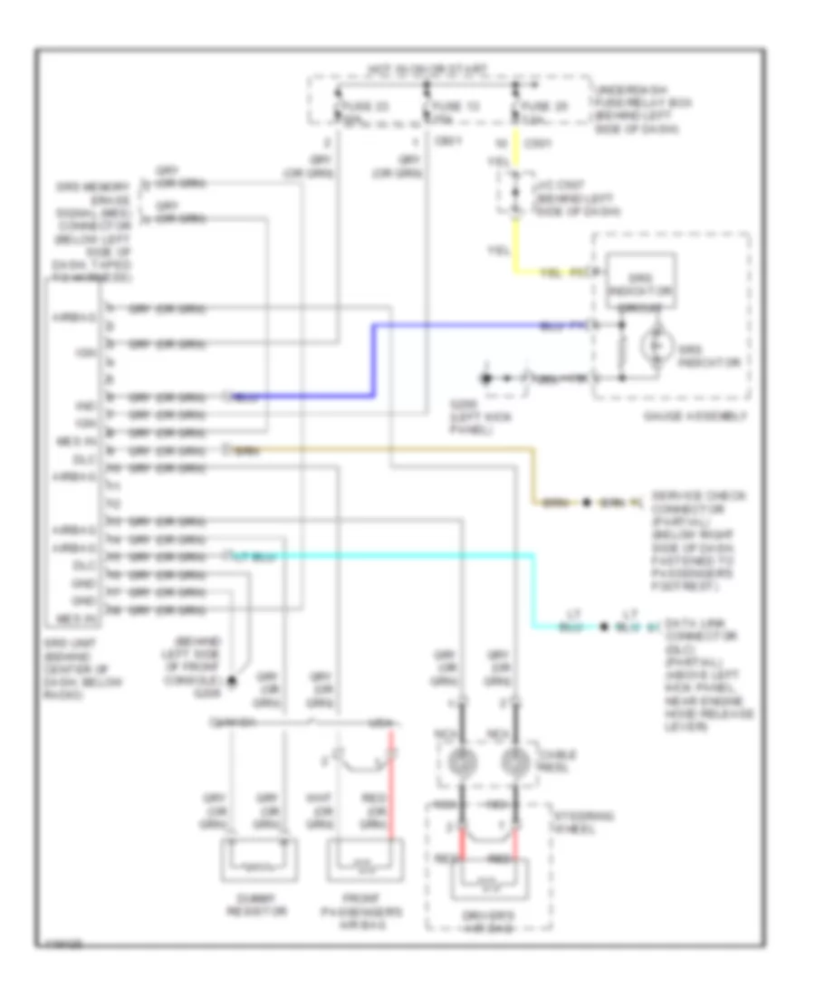
SUPPLEMENTAL RESTRAINTS
Supplemental Restraint Wiring Diagram for Honda Civic VP 1999
List of elements for Supplemental Restraint Wiring Diagram for Honda Civic VP 1999:
AIR CONDITIONINGCRUISE CONTROLCOMPUTER DATA LINESANTI-LOCK BRAKESANTI-THEFTBODY COMPUTERENGINE PERFORMANCECOOLING FANHORNEXTERIOR LIGHTSDEFOGGERSHEADLIGHTSPOWER DISTRIBUTIONINSTRUMENT CLUSTERGROUND DISTRIBUTIONINTERIOR LIGHTSPOWER DOOR LOCKSSTARTING/CHARGINGPOWER TOP/SUNROOFPOWER WINDOWSRADIOPOWER MIRRORSSHIFT INTERLOCKSWARNING SYSTEMSTRANSMISSIONSUPPLEMENTAL RESTRAINTSWIPER/WASHER