SUPPLEMENTAL RESTRAINTS
Supplemental Restraint Wiring Diagram for Honda Odyssey LX 1998
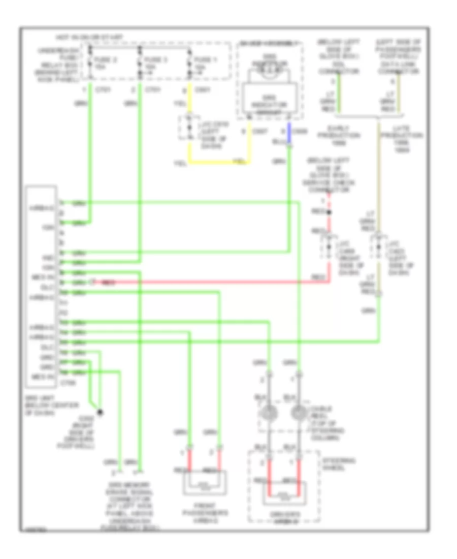
List of elements for Supplemental Restraint Wiring Diagram for Honda Odyssey LX 1998:
- (below left side of glove box) sdl connector
- (below left side of glove box) service check connector
- (left side of passenger's footwell) data link connector
- Airbag
- C601
- C607
- C609
- C701
- C706
- Cable reel (top of steering column)
- Dlc
- Driver's airbag
- Early production
- Front passenger's airbag
- Fuse 1 10a
- Fuse 2 15a
- Fuse 3 10a
- G302 (right side of driver's footwell)
- Gauge assembly
- Grd
- Hot in on or start
- Ign
- Ind
- J/c c423 (left side of dash)
- J/c c469 (right side of dash)
- J/c c610 (left side of dash)
- Late production 1998,
- Mes in
- Red
- Srs indicator
- Srs indicator circuit
- Srs memory erase signal connector (at left kick panel, above underdash fuse/relay box)
- Srs unit (below center of dash)
- Steering wheel
- Underdash fuse/ relay box (behind left kick panel)
 English