
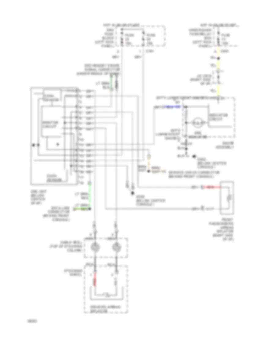
SUPPLEMENTAL RESTRAINTS
Supplemental Restraint Wiring Diagram for Honda Prelude Si 1994
List of elements for Supplemental Restraint Wiring Diagram for Honda Prelude Si 1994:
AIR CONDITIONINGANTI-LOCK BRAKESANTI-THEFTCOMPUTER DATA LINESCOOLING FANDEFOGGERSELECTRONIC POWER STEERINGENGINE PERFORMANCECRUISE CONTROLGROUND DISTRIBUTIONHEADLIGHTSEXTERIOR LIGHTSHORNPOWER DOOR LOCKSINSTRUMENT CLUSTERINTERIOR LIGHTSPOWER DISTRIBUTIONPOWER TOP/SUNROOFPOWER MIRRORSRADIOPOWER ANTENNAPOWER WINDOWSPOWER SEATSSUPPLEMENTAL RESTRAINTSTRANSMISSIONSHIFT INTERLOCKSSTARTING/CHARGINGWARNING SYSTEMSWIPER/WASHER